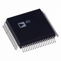
AD1843JS Analog Devices Inc, AD1843JS Datasheet - Page 56

AD1843JS
Manufacturer Part Number
AD1843JS
Description
IC CODEC STEREO 5V 16BIT 80PQFP
Manufacturer
Analog Devices Inc
Type
Stereo Audior
Datasheet
1.AD1843JS.pdf
(64 pages)
Specifications of AD1843JS
Rohs Status
RoHS non-compliant
Data Interface
Serial
Resolution (bits)
16 b
Number Of Adcs / Dacs
1 / 2
Sigma Delta
Yes
S/n Ratio, Adcs / Dacs (db) Typ
92 / 86
Dynamic Range, Adcs / Dacs (db) Typ
85 / 80
Voltage - Supply, Analog
4.75 V ~ 5.25 V
Voltage - Supply, Digital
2.85 V ~ 5.25 V
Operating Temperature
0°C ~ 70°C
Mounting Type
Surface Mount
Package / Case
80-MQFP, 80-PQFP
Available stocks
Company
Part Number
Manufacturer
Quantity
Price
Part Number:
AD1843JS
Manufacturer:
ADI/亚德诺
Quantity:
20 000
AD1843
“room” in the frequency domain for a second pole, especially in
modem applications, where the signal bandwidth is 4.2 kHz. A
suggested capacitor value is 120 pF when using the 10K op amp
feedback resistor as shown, for a –3 dB point of approximately
133 kHz. Note that the combined effect of both filters causes a
gain error of approximately 0.1% at 4.2 kHz.
The AD1843 Codec contains an optional +20 dB gain block to
accommodate condenser microphones. Particular system re-
quirements will depend upon the characteristics of the intended
microphone. Figure 22 illustrates one example of how an elec-
tret condenser mic requiring phantom power could be con-
nected to the AD1843. CMOUT is shown buffered by an op
amp; the current drawn from CMOUT should be as minimal as
possible. Note that if a battery-powered microphone is used,
the buffer and R2s are not needed. The values of R1, R2, and
C should be chosen in light of the mic characteristics and in-
tended gain. Typical values for these might be R1 = 20 k ,
R2 = 2 k , and C = 220 pF. Figure 22 shows a voltage follower
buffer on the CMOUT signal. The output of this buffer,
CMBUF, can be used in any circuit which needs the common-
mode bias point from the AD1843’s on-chip voltage reference.
The AD820 is a JFET input op amp whose very high imped-
ance inputs present essentially no load on the CMOUT output
from the AD1843.
Connect unused analog inputs to CMBUF or leave them
unconnected; do not connect unused analog inputs to
either analog power or ground!
Figure 23 shows ac-coupled line outputs. The resistors are used
to center the output signals around analog ground. If dc-
coupling is desired, CMOUT could be used with op amps as
mentioned above, if desired.
SOURCE
RIGHT ELECTRET
Figure 22. AD1843 “Phantom-Powered” Microphone
Input Circuit
LEFT ELECTRET
MICROPHONE
MICROPHONE
CONDENSER
CONDENSER
Figure 21. Single-Ended to Differential Converter
INPUT
INPUT
1µF
CMBUF
10k
SSM2135
1/2
10k
CLOSE TO SOURCE
R2
R2
CMBUF
10k
1µF
1µF
CMBUF
1/2 AD820
SSM2135
10k
5k
5k
1/2
1/2 SSM2135
OR AD820
1µF
R1
R1
C
C
1/2 SSM2135
CLOSE TO AD1843
OR AD820
0.9k
1µF
0.33µF
0.33µF
1000pF
NPO
MICL
CMOUT
MICR
LINLP
LINRP
LINRN
LINLN
–56–
For optimal performance, the AD1843 DAC2 output has provi-
sion for a differential configuration. A simple differential-to-
single-ended conversion circuit is shown in Figure 24. The
noise rejection of this circuit is limited by the match of the R
and R
nents. The equation that determines the output voltage is as
follows:
For maximum noise immunity, this circuit should be located in
close proximity to where V
receiver option is the SSM2141, which provides better matching
than a discrete implementation.
Figure 24. AD1843 Differential-to-Single-Ended Converter
Line Output Connections
A circuit for headphone drive is illustrated in Figure 25. The
AD1843 headphone output is designed to drive loads of 32
ohms or smaller (i.e., higher impedance). If larger loads are
used (e.g., 16 ohms or 8 ohms), the analog output will be dis-
torted for large output signals because of current limiting.
“Walkman”-type headphone impedances are generally around
32 ohms. Telephone handset impedances are typically 150 ohms.
Figure 26 shows an example circuit for the mono output
(MOUT) from the AD1843. The OP279 is a single +5 V supply
op amp which can drive a small 8 ohm or 16 ohm speaker to
modest levels.
CMBUF
LOUT2LN
LOUT2LP
(V–)
(V+)
Figure 23. AD1843 (Single-Ended) Line Output
Connections
Figure 25. AD1843 Headphone Drive Connections
f
SSM2135
resistors. The resistors should be 1% tolerance compo-
1/2
R
R
10pF
i
i
LOUT2RP
LOUT2LP
HPOUTR
HPOUTC
HPOUTL
V
LOUT1R
LOUT1L
O
R
= (R
f
10pF
R
SSM2135
f
1/2
f
/R
O
i
)(V+) – (R
is processed. Another differential
V
O
1µF
1µF
CMBUF
LOUT2RN
LOUT2RP
(V+)
(V–)
f
SSM2135
47k
47k
/R
1/2
i
)(V–)
R
R
10pF
i
i
R
f
10pF
SSM2135
R
f
1/2
REV. 0
i
V
O


