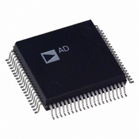
AD1843JS Analog Devices Inc, AD1843JS Datasheet - Page 58

AD1843JS
Manufacturer Part Number
AD1843JS
Description
IC CODEC STEREO 5V 16BIT 80PQFP
Manufacturer
Analog Devices Inc
Type
Stereo Audior
Datasheet
1.AD1843JS.pdf
(64 pages)
Specifications of AD1843JS
Rohs Status
RoHS non-compliant
Data Interface
Serial
Resolution (bits)
16 b
Number Of Adcs / Dacs
1 / 2
Sigma Delta
Yes
S/n Ratio, Adcs / Dacs (db) Typ
92 / 86
Dynamic Range, Adcs / Dacs (db) Typ
85 / 80
Voltage - Supply, Analog
4.75 V ~ 5.25 V
Voltage - Supply, Digital
2.85 V ~ 5.25 V
Operating Temperature
0°C ~ 70°C
Mounting Type
Surface Mount
Package / Case
80-MQFP, 80-PQFP
Available stocks
Company
Part Number
Manufacturer
Quantity
Price
Part Number:
AD1843JS
Manufacturer:
ADI/亚德诺
Quantity:
20 000
AD1843
Good, standard engineering practices should be applied for
power-supply decoupling. Decoupling capacitors should be
placed as close as possible to package pins. If a separate analog
power supply is not available, we recommend the circuit shown
in Figure 33 for using a single +5 V supply. This circuitry
should be as close to the supply pins as is practical.
Figure 34 illustrates an optional circuit for generating the +5 V
analog supply for the AD1843. The +12 V rail available on the
ISA bus can be regulated down to +5 V using an ordinary 7805
three-terminal regulator and the bypassing and decoupling
capacitors shown. The digital supply should still be decoupled
and bypassed as shown above in Figure 33.
SUPPLY
PC 0 V
Figure 34. AD1843 Optional Analog Supply Regulation
+12V
+5V
Bypassing
Figure 33. AD1843 Recommended Power Supply
10µF
DGND
FERRITE OR
FERRITE OR
INDUCTOR
INDUCTOR
SUITABLE
SUITABLE
220nF
0.1µF
0.1µF
FERRITE
BEAD
V
DD
1µF
1µF
10µF
0.1µF
1.6
V
DD
V
220nF
DD
0.1µF
0.1µF
1µF
V
IN
DD
V
GND
7805
DD
OUT
0.1µF
AGND
0.1µF
0.1µF
V
DD
V
DD
1µF
V
0.1µF
CC
0.1µF
V
220nF
DD
V
V
CC
DD
0.1µF
0.1µF
V
+5VA
CC
–58–
Analog Devices recommends a split ground plane as shown in
Figure 35a (PQFP) and Figure 35b (TQFP). The analog plane
and the digital plane are connected directly under the AD1843.
Splitting the ground plane directly under the SoundComm
Codec is optimal because analog pins will be located above the
analog ground plane and digital pins will be located directly
above the digital ground plane for the best isolation. The digital
ground and analog ground should be tied together in the vicin-
ity of the AD1843. Other schemes may also yield satisfactory
results. If the split ground plane recommended here is not pos-
sible, the AD1843 should be entirely over the analog ground
plane.
Figure 35b. AD1843 Recommended TQFP Ground Plane
Figure 35a. AD1843 Recommended PQFP Ground Plane
GROUND
GROUND
DIGITAL
DIGITAL
PLANE
PLANE
AD1843
AD1843
50
10
62
13
14
49
11
61
PQFP
TQFP
GROUND
GROUND
ANALOG
ANALOG
PLANE
PLANE
REV. 0


