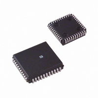
AD1849KP-REEL Analog Devices Inc, AD1849KP-REEL Datasheet - Page 16

AD1849KP-REEL
Manufacturer Part Number
AD1849KP-REEL
Description
IC CODEC STEREO 5V 16BIT 44PLCC
Manufacturer
Analog Devices Inc
Type
Stereo Audior
Datasheet
1.AD1849KP.pdf
(28 pages)
Specifications of AD1849KP-REEL
Rohs Status
RoHS non-compliant
Data Interface
Serial
Resolution (bits)
16 b
Number Of Adcs / Dacs
2 / 2
Sigma Delta
Yes
Dynamic Range, Adcs / Dacs (db) Typ
83 / 86
Voltage - Supply, Analog
4.75 V ~ 5.25 V
Voltage - Supply, Digital
4.75 V ~ 5.25 V
Operating Temperature
0°C ~ 70°C
Mounting Type
Surface Mount
Package / Case
44-PLCC
Note that all these defaults can be changed with control information in the first Data Word. Note also that the PIO bits in the output
serial streams always reflect the values most recently read from the external PIO pins. (See “Parallel I/O Bits” below for timing
details.) A Control-to-Data Mode transition is no exception.
An important consequence of these defaults is that the AD1849K Codec always comes out of reset or power down in slave mode with an
externally supplied serial bit clock (SCLK) as the clock source. An external device must supply the serial bit clock and the chaining word
input signal (TSIN) initially. (See “Codec Startup, Modes, and Transitions” below for more details.)
AD1849K
Control Register Defaults
Upon coming out of RESET or Power Down, internal control registers will be initialized to the following values:
Defaults Calming Out of RESET or Power Down
MB
OLB
DCB
AC
DFR2:0
ST
DF1:0
ITS
MCK2:0
FSEL1:0
MS
TXDIS
ENL
ADL
PIO1:0
OM1:0
LO5:0
ADI
SM
RO5:0
OVR
IS
LG3:0
MA3:0
RG3:0
Also, when making a transition from Control Mode to Data Mode, those control register values that are not changeable in Control
Mode get reset to the defaults above (except PIO). The control registers that can be changed in Control Mode will have the values
they were just assigned. The subset of the above list of control registers that are assigned default values on the transition from
Control Mode to Data Mode are:
Defaults at a Control-to-Data Mode Transition
OM1:0
LO5:0
SM
RO5:0
OVR
IS
LG3:0
MA3:0
RG3:0
0
63
0
63
0
0
0
15
0
Mute Line 0 and Line 1
Mute Left DAC
Mute Mono Speaker
Mute Right DAC
No Overrange
Line-Level Stereo Inputs
No Gain
No Mix
No Gain
0
0
1
0
0
0
1
0
0
2
0
1
0
0
3
0
63
1
0
63
0
0
0
15
0
Mic Input Applied to 20 dB Fixed Gain Block
Full-Scale Line 0 Output 2.8 V p-p, Full-Scale Line 1 Output 4.0 V p-p, Full-Scale Mono Speaker
Output 8.0 V p-p
Data/Control Bit HI
Autocalibration Disabled
8 or 5.5125 kHz
Monophonic Mode
8-Bit µ-Law Data
FSYNC, SDTX and SCLK Three-State within 3 SCLK Cycles after D/C Goes LO
Serial Bit Clock [SCLK] is the Master Clock
256 Bits per Frame
Slave Mode
Three-State Serial Data Output
Loopback Disabled
Digital Loopback
“1”s, i.e., Three-State for the Open Collector Outputs
Mute Line 0 and Line 1 Outputs
Mute Left DAC
ADC Data Invalid, Autocalibration in Progress
Mute Mono Speaker
Mute Right DAC
No Overrange
Line-Level Stereo Inputs
No Gain on Left Channel
No Mix
No Gain on Right Channel


