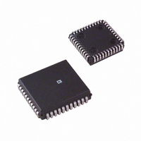
AD1849KP-REEL Analog Devices Inc, AD1849KP-REEL Datasheet - Page 22

AD1849KP-REEL
Manufacturer Part Number
AD1849KP-REEL
Description
IC CODEC STEREO 5V 16BIT 44PLCC
Manufacturer
Analog Devices Inc
Type
Stereo Audior
Datasheet
1.AD1849KP.pdf
(28 pages)
Specifications of AD1849KP-REEL
Rohs Status
RoHS non-compliant
Data Interface
Serial
Resolution (bits)
16 b
Number Of Adcs / Dacs
2 / 2
Sigma Delta
Yes
Dynamic Range, Adcs / Dacs (db) Typ
83 / 86
Voltage - Supply, Analog
4.75 V ~ 5.25 V
Voltage - Supply, Digital
4.75 V ~ 5.25 V
Operating Temperature
0°C ~ 70°C
Mounting Type
Surface Mount
Package / Case
44-PLCC
AD1849K
A circuit for 2 V rms line-level inputs is shown in Figure 11.
Note that this is approximately a divide-by-two resistive divider.
An external passive antialias filter is required. If line-level inputs
are already at the 1 V rms levels expected by the AD1849K, the
resistors in parallel with the 560 pF capacitors should be
omitted and the series 5.1 kΩ resistor should be decreased to
2.5 kΩ.
The AD1849K Codec contains a bypassable 20 dB gain block
to accommodate condenser microphones. Particular system
requirements will depend upon the characteristics of the
intended microphone. Figure 12 illustrates one example of how
an electret condenser mike requiring phantom power could be
connected to the AD1849K. CMOUT is shown buffered by an
op amp; a transistor like a 2N4124 will also work fine for this
purpose. Note that if a battery-powered microphone is used, the
buffer and R2s are not needed. The values of R1, R2, and C
should be chosen in light of the mic characteristics and intended
gain. Typical values for these might be R1 = 20 kΩ, R2 = 2 kΩ,
and C = 220 pF.
Figure 13 shows ac-coupled line outputs. The resistors are
used to center the output signals around analog ground. If
dc-coupling is desired, CMOUT could be used with op amps
as mentioned below.
RIGHT ELECTRET
LEFT ELECTRET
MICROPHONE
MICROPHONE
CONDENSER
CONDENSER
INPUT
INPUT
R2
R2
5.1k
5.1k
560pF
560pF
NPO
NPO
1 F
1 F
5k
5.1k
5.1k
5k
0.33 F
0.33 F
1/2 SSM2135
OR AD820
R1
R1
C
C
1/2 SSM2135
OR AD820
1/2 SSM2135
OR AD820
LINL
LINR
0.33 F
0.33 F
MINL
CMOUT
MINR
CMOUT
A circuit for headphone drive is illustrated in Figure 14. Drive is
supplied by 5 V operational amps. The circuit shown ac couples
the headphones to the line output.
The AD1849K has a common return path LOUT1C which is
biased up to the CMOUT voltage, nominally 2.25 V. The
AD1849K allows for 6 dB larger output voltage swings by
resetting the OLB bit (Bit 59 of the Control Word) to “0.”
Figure 15 illustrates an alternative headphone connection for
the AD1849K which uses the LOUT1C pin to eliminate the
need for ac coupling. The 12 Ω resistors minimize output level
variations caused by different headphone impedances. LOUT1L,
LOUT1R and LOUT1C are short-circuit protected. Note that
driving headphones directly as shown in Figure 15 with OLB =
0 will cause clipping for large input signals and will only work
with very efficient “Walkman-type” headphones. For high
quality headphone listening, Analog Devices recommends the
circuit shown in Figure 14 with OLB = 1.
LOUT1C
LOUT1R
LOUT1L
LOUT1R
LOUT1C
LOUT1L
LOUT0R
LOUT0L
10k
10k
12
12
SSM2135
1 F
1 F
8.66k
8.66k
1/2W
1/2W
47k
47k
470 F
470 F
HEADPHONE
LEFT
HEADPHONE
RIGHT
HEADPHONE
RETURN
HEADPHONE
LEFT
HEADPHONE
RIGHT


