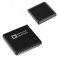
AD1845JPZ Analog Devices Inc, AD1845JPZ Datasheet - Page 27

AD1845JPZ
Manufacturer Part Number
AD1845JPZ
Description
IC CODEC STEREO 5V 16BIT 68PLCC
Manufacturer
Analog Devices Inc
Type
Stereo Audior
Datasheet
1.AD1845JP.pdf
(40 pages)
Specifications of AD1845JPZ
Resolution (bits)
16 b
Number Of Adcs / Dacs
2 / 2
Sigma Delta
Yes
Dynamic Range, Adcs / Dacs (db) Typ
81 / 82
Voltage - Supply, Analog
4.75 V ~ 5.25 V
Voltage - Supply, Digital
4.75 V ~ 5.25 V
Operating Temperature
0°C ~ 70°C
Mounting Type
Surface Mount
Package / Case
68-PLCC
Single Supply Voltage (typ)
5V
Single Supply Voltage (min)
4.75V
Single Supply Voltage (max)
5.25V
Package Type
PLCC
Lead Free Status / RoHS Status
Lead free / RoHS Compliant
res
FREN
MIXPWD
DACPWD
ADCPWD
This register’s initial state after reset is “000x 0xxx.”
NOTE: Changing CFMT[1:0], CC/L, CS/M, requires the Mode Change Enable (MCE) state or setting CEN = 0.
res
CS/M
CC/L
CFMT[1:0]
This register’s initial state after reset is “0000 xxxx.”
TOTPWD
res
REV. C
Power-Down Control Register (IXA3:0 = 27)
Crystal, Clock Select/Total Power-Down Register (IXA3:0 = 29)
Capture Data Format Control Register (IXA3:0 = 28)
IXA3:0
IXA3:0
CFMT1
0
0
0
0
1
1
1
1
IXA3:0
27
29
28
Frequency Select Register Enable. In MODE2, selecting this bit will turn on the Frequency Select Registers (see
Mixer Power Down. The DAC and the output mixer are powered down, and the DAC sample clock is turned off.
DAC Power Down. The DAC is powered down and the DAC sample clock is turned off.
ADC Power Down. The ADC is powered down and the ADC sample clock is turned off.
Capture Stereo/Mono Select. Setting this bit determines how the captured audio data will be formatted. In the
Capture Companding/Linear Select. This bit is set to determine linear, -Law or A-Law companding. See Figure
Capture Data Format. This bit is set to format the data being captured in MODE 2. See Figure 12 for CFMT
Total Power Down. When TOTPWD = HI, the ADC, DAC, mixer, and voltage reference are powered down, and
Reserved for future expansion. Always write zeros to these bits.
indirect registers 22 and 23) and disable CFS2:0.
0
1
Reserved for future expansion. Always write zeros to these bits.
Mono mode, valid information is captured on the “left” channel, and the “right” channel data is not valid.
0
1
12 for CFMT[1:0] and CC/L bit settings that determine the audio data type capture format.
and CC/L bit settings that determine the capture audio data type format.
the ADC and DAC sample clocks are turned off. Only the digital interface remains active to allow the host to exit
the AD1845 from the total power-down state.
Reserved for future expansion. Always write zeros to these bits.
ADCPWD
CFMT1
Data 7
Data 7
Data 7
XFS2
CFS Active.
Frequency Select Registers Active, CFS disabled.
Mono Format
Stereo Format
CFMT0
0
0
1
1
0
0
1
1
DACPWD
CFMT0
Data 6
Data 6
Data 6
XFS1
CC/L
0
1
0
1
0
1
0
1
Figure 12. Capture Audio Data Type
MIXPWD
Data 5
Data 5
Data 5
XFS0
CC/L
Audio Data Type
Linear, 8-Bit Unsigned PCM
Linear, 16-Bit Twos Complement PCM Little Endian
A-Law, 8-Bit Companded
Reserved
Reserved
Linear, 16-Bit Twos-Complement Big Endian
Reserved
-Law, 8-Bit Companded
–27–
Data 4
Data 4
Data 4
CS/M
res
res
Data 3
Data 3
Data 3
FREN
res
res
Data 2
Data 2
Data 2
res
res
res
Data 1
Data 1
Data 1
res
res
res
TOTPWD
Data 0
Data 0
AD1845
Data 0
res
res


