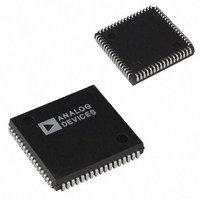
AD1845JPZ Analog Devices Inc, AD1845JPZ Datasheet - Page 20

AD1845JPZ
Manufacturer Part Number
AD1845JPZ
Description
IC CODEC STEREO 5V 16BIT 68PLCC
Manufacturer
Analog Devices Inc
Type
Stereo Audior
Datasheet
1.AD1845JP.pdf
(40 pages)
Specifications of AD1845JPZ
Resolution (bits)
16 b
Number Of Adcs / Dacs
2 / 2
Sigma Delta
Yes
Dynamic Range, Adcs / Dacs (db) Typ
81 / 82
Voltage - Supply, Analog
4.75 V ~ 5.25 V
Voltage - Supply, Digital
4.75 V ~ 5.25 V
Operating Temperature
0°C ~ 70°C
Mounting Type
Surface Mount
Package / Case
68-PLCC
Single Supply Voltage (typ)
5V
Single Supply Voltage (min)
4.75V
Single Supply Voltage (max)
5.25V
Package Type
PLCC
Lead Free Status / RoHS Status
Lead free / RoHS Compliant
AD1845
NOTE: Placing the AD1845 in the Mode Change Enable (MCE) state is not required when changing the CEN and PEN bits in this
register.
PEN
CEN
SDC
ACAL
res
PPIO
CPIO
This register’s initial state after reset is “00xx 1000.”
INITD
IEN
res
Interface Configuration Register (IXA3:0 = 9)
Pin Control Register (IXA3:0 = 10)
IXA3:0
IXA3:0
10
9
Playback Enable. This bit will enable the playback of data in the format selected. The AD1845 will generate
PDRQ and respond to PDAK signals when this bit is enabled and PPIO = 0. If PPIO = 1, this bit enables Pro-
grammed I/O (PIO) playback mode.
0
1
Capture Enable. This bit will enable the capture of data in the format selected. The AD1845 will generate
CDRQ and respond to CDAK signals when this bit is enabled and CPIO = 0. If CPIO = 1, this bit enables PIO
capture mode.
0
1
Single DMA Channel. This bit will force both capture and playback DMA requests to occur on the Playback
DMA channel. The Capture DMA CDRQ pin will be LO. This bit will allow the AD1845 to be used with only
one DMA channel. Simultaneous capture and playback cannot occur in this mode. Should both capture and
playback be enabled (CEN=PEN=1) in the mode, only playback will occur. See “Data and Control Transfers” for
further explanation.
0
1
Autocalibrate Enable. This bit determines whether the AD1845 performs an autocalibration whenever the Mode
Change Enable (MCE) bit changes from HI to LO. See “Autocalibration” for a description of a complete
autocalibration sequence. Note that an autocalibration is forced whenever the RESET or PWRDWN pin is
asserted LO then transitions HI regardless of the state of the ACAL bit.
0
1
Reserved for future expansion. Always write zeros to these bits.
Playback PIO Enable. This bit determines whether the playback data is transferred via DMA or PIO.
0
1
Capture PIO Enable. This bit determines whether the capture data is transferred via DMA or PIO.
0
1
Disable setting the INIT bit after changing the sample rate in MODE1. Otherwise the INIT bit is set HI for
approximately 200 s after changing the sample rate.
0
1
Interrupt Enable. This bit enables the interrupt pin. The Interrupt Pin will go active HI when the number of
samples programmed in the Base Count Register is reached.
0
1
Reserved for future expansion. Always write zeros to these bits.
XCTL1
Data 7
Data 7
CPIO
Playback disabled (PDRQ and PIO Playback Data Register inactive)
Playback enabled
Capture disable (CDRQ and PIO Capture Data Register inactive)
Capture enable
Dual DMA channel mode
Single DMA channel mode
No autocalibration
Autocalibration after mode change
DMA transfers only
PIO transfers only
DMA transfers only
PIO transfers only
INIT bit is enabled
INIT bit is disabled
Interrupt disabled
Interrupt enabled
XCTL0
Data 6
Data 6
PPIO
Data 5
Data 5
res
res
–20–
Data 4
Data 4
res
res
Data 3
ACAL
Data 3
res
Data 2
Data 2
SDC
res
Data 1
Data 1
CEN
IEN
Data 0
Data 0
INITD
PEN
REV. C


