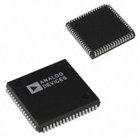
AD1845JPZ Analog Devices Inc, AD1845JPZ Datasheet - Page 34

AD1845JPZ
Manufacturer Part Number
AD1845JPZ
Description
IC CODEC STEREO 5V 16BIT 68PLCC
Manufacturer
Analog Devices Inc
Type
Stereo Audior
Datasheet
1.AD1845JP.pdf
(40 pages)
Specifications of AD1845JPZ
Resolution (bits)
16 b
Number Of Adcs / Dacs
2 / 2
Sigma Delta
Yes
Dynamic Range, Adcs / Dacs (db) Typ
81 / 82
Voltage - Supply, Analog
4.75 V ~ 5.25 V
Voltage - Supply, Digital
4.75 V ~ 5.25 V
Operating Temperature
0°C ~ 70°C
Mounting Type
Surface Mount
Package / Case
68-PLCC
Single Supply Voltage (typ)
5V
Single Supply Voltage (min)
4.75V
Single Supply Voltage (max)
5.25V
Package Type
PLCC
Lead Free Status / RoHS Status
Lead free / RoHS Compliant
AD1845
In the Expanded Mode, MODE2, the AD1845 can be pro-
grammed to change the sample rate selection in 1 Hz incre-
ments “on the fly” and without entering the Mode Change
Enable Sequence. The following sequence applies to the
AD1845 in MODE2 only:
APPLICATIONS CIRCUITS
The AD1845 Stereo Codec has been designed to require a
minimum of external circuitry. The recommended circuits are
shown in Figures 27 through 35.
See Figure 1 for an illustration of the connection between the
AD1845 SoundPort Codec and the Industry Standard Archi-
tecture (ISA) computer bus, also known as the “PC-AT bus.”
Note that the 74_245 transceiver receives its enable and direc-
tion signals directly from the Codec. Analog Devices recom-
mends using the “slowest” 74_245 adequately fast to meet all
AD1845 and computer bus timing and drive requirements. So
doing will minimize switching transients of the 74_245. This in
turn will minimize the digital feed through effects of the trans-
ceiver when driving the AD1845, which can cause the audio
noise floor to rise. In most applications, the 74_245 can be
omitted and the AD1845 connected directly ISA bus taking
advantage of the AD1845’s built-in 16 mA drivers.
Industry-standard compact disc “line-levels” are 2 V rms cen-
tered around analog ground. (For other audio equipment, “line
level” is much more loosely defined.) The AD1845 SoundPort
is a +5 V only powered device. Line level voltage swings for the
AD1845 are defined to be 1 V rms for a sine wave ADC input
and user selectable 0.707 V rms or 1 V rms for a sine wave
DAC output. Thus, 2 V rms input analog signals must be
attenuated and either centered around the reference voltage
intermediate between 0 V and +5 V or ac coupled. The V
pin will be at this intermediate voltage, nominally 2.25 V. It has
limited drive but can be used as a voltage datum to an op amp
input. Note, however, that dc-coupled inputs are not recom-
mended, as they provide no performance benefits with the
AD1845 architecture. Furthermore, dc offset differences be-
tween multiple dc-coupled inputs create the potential for
“clicks” when changing the input mixer selection.
A circuit for 2 V rms mono, line-level inputs and auxiliaries is
shown in Figure 27 and Figure 28. Note that this is a divide-
by-two resistive dividers considering the codec input imped-
ance. The input resistor and 560 pF (1000 pF) capacitor
provides the single-pole of antialias filtering required for the
ADCs. If line-level inputs are already at the 1 V rms levels
expected by the AD1845, the resistors in parallel with the
560 pF (1000 pF) capacitors can be omitted. If the application
does not route the AUX2 inputs to the ADCs, then no antialias
filtering is required (only the 1 F ac coupling capacitor).
• Enable the Frequency Select Register by setting FREN to 1.
• Change the Lower and Upper Frequency Select Register,
FU7:0 and FL7:0.
REF
–34–
Figure 27. 2 V rms Line-Level Input Circuit for LINE Inputs
The AD1845 codec contains an optional +20 dB gain block to
accommodate condenser microphones. Particular system re-
quirements will depend upon the characteristics of the intended
microphone. Figure 29 illustrates one example of how an elec-
tret condenser mike requiring phantom power could be con-
nected to the AD1845. V
transistor like a 2N4124 will also work fine for this purpose.
Note that if a battery-powered microphone is used, the buffer
and R2s are not needed. The values of R1, R2, and C should be
chosen in light of the mic characteristics and intended gain.
Typical values for these might be R1 = 20 k , R2 = 2 k , and
C = 220 pF.
LEFT ELECTRET
RIGHT ELECTRET
Figure 29. “Phantom-Powered” Microphone Input
Circuit
Figure 28. 2 V rms Line-Level Input Circuit for M_IN and
AUX Inputs
MICROPHONE
CONDENSER
MICROPHONE
CONDENSER
INPUT
INPUT
R2
R2
1000pF
1000pF
3.3k
3.3k
NPO
3.3k
560pF
3.3k
560pF
NPO
NPO
NPO
1 F
1 F
REF
5k
5k
is shown buffered by an op amp; a
4.3k
4.3k
4.3k
4.3k
1 F
1 F
1/2 SSM2135 OR AD820
1 F
1 F
R1
C
R1
C
R_AUX1
R_AUX2
L_AUX1
L_AUX2
M_IN
1/2 SSM2135
1/2 SSM2135
OR AD820
L_LINE
R_LINE
OR AD820
0.33 F
0.33 F
V
REV. C
L_MIC
R_MIC
V
REF
REF


