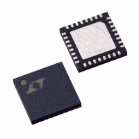
LTC1955EUH Linear Technology, LTC1955EUH Datasheet

LTC1955EUH
Specifications of LTC1955EUH
Available stocks
Related parts for LTC1955EUH
LTC1955EUH Summary of contents
Page 1
... ESD in-situ with no additional components. The LTC1955 is available in a low profi le (0.75mm) 5mm × 5mm QFN package. LT, LTC and LTM are registered trademarks of Linear Technology Corporation. All other trademarks are the property of their respective owners. Protected by U.S. Patents, including 6356140, 6411531. ...
Page 2
... LTC1955IUH#PBF LTC1955IUH#TRPBF LEAD BASED FINISH TAPE AND REEL LTC1955EUH LTC1955EUH#TR LTC1955IUH LTC1955IUH#TR Consult LTC Marketing for parts specifi ed with wider operating temperature ranges. *The temperature grade is identifi label on the shipping container. For more information on lead free part marking, go to: For more information on tape and reel specifi ...
Page 3
ELECTRICAL CHARACTERISTICS temperature range, otherwise specifi cations are at T PARAMETER I Operating Current DVCC I Shutdown Current DVCC Charge Pump R 5V Mode Open-Loop Output Resistance OLCP CPO Turn-On Time Smart Card Supplies CCA CCB V ...
Page 4
LTC1955 ELECTRICAL CHARACTERISTICS temperature range, otherwise specifi cations are at T PARAMETER D OUT Low Level Output Voltage ( High Level Output Voltage ( UNDERV Threshold Leakage Current FAULT Low Level Output Voltage ( ...
Page 5
TYPICAL PERFORMANCE CHARACTERISTICS No Load Supply Current vs V BATT 600 T = 25° 0μA CCA CCB 500 CCA CCB 400 V = 1.8V 300 CCA CCB ...
Page 6
LTC1955 TYPICAL PERFORMANCE CHARACTERISTICS Charge Pump and LDO Activation V CPO 5V/DIV V CCA 5V/DIV I/O A 5V/DIV 1955 G10 1ms/DIV PIN FUNCTIONS SV : Power. Supply voltage for analog sections of the BATT LTC1955 Power. Supply voltage ...
Page 7
PIN FUNCTIONS SCLK: Input. The SCLK pin clocks the serial port. Each new data bit is received on the rising edge of SCLK. SCLK should be left high during idle times and should not be clocked when LD is low. ...
Page 8
LTC1955 BLOCK DIAGRAM 17 V CCB 20 I/O B SMART 18 CLK B CARD SOCKET B 19 RST B 21 PRES B 29 DATA 31 SMART ASYNC CARD 32 SYNC COMMUNICATIONS SERIAL PORT 28 ...
Page 9
OPERATION Serial Port The microcontroller compatible serial port provides all of the command and control inputs for the LTC1955, as well as the status of the two smart cards. Data on the D input is loaded on the rising edge ...
Page 10
LTC1955 OPERATION Table 1. Serial Port Comand STATUS OUTPUT BIT COMMAND INPUT CARD CCB (See Table Card B Select/Deselect 0 D3 Data Pull-Up Defeat Card B Electrical Fault D4 Reserved (Always ...
Page 11
OPERATION Table 4. Card A Communications Options D12 D11 CARD A COMMUNICATION MODE 0 0 Nothing Selected 0 1 C4A Connected to DATA Pin 1 0 C8A Connected to DATA Pin 1 1 I/O A Connected to DATA Pin Note ...
Page 12
LTC1955 OPERATION Smart Card Detection Circuits The PRES A/PRES B pins are used to detect the presence of a smart card. An automatic debounce circuit waits until a smart card has been present for a continuous period of typically 35ms. ...
Page 13
OPERATION V /V undervoltage faults are determined by compar- CCA CCB ing the actual output voltage with the internal reference voltage. If the output is more than ~5% below its set point for the entire timeout period, the fault is ...
Page 14
LTC1955 APPLICATIONS INFORMATION 10kV ESD Protection All smart card pins (CLK A/CLK B, RST A/RST B, I/O A/I/O B, C4A, C8A and can withstand over 10kV of CCA CCB human body model ESD in-situ. In order to ...
Page 15
APPLICATIONS INFORMATION Interfacing to a Microcontroller The serial port of the LTC1955 can be connected directly to a 68HC11 style microcontroller’s serial port. The mcro- controller should be confi gured as the master device and its clock’s idle state should ...
Page 16
LTC1955 APPLICATIONS INFORMATION Using S.A.M. Cards For applications using one or more installed S.A.M. cards, the PRES A/PRES B pins for those sockets must be grounded before operation of the card can occur (assuming NC/NO is grounded). The PRES A/PRES ...
Page 17
APPLICATIONS INFORMATION DV and V when in shutdown. For applications that CC BATT require virtually zero shutdown current, the DV be grounded. This will reduce the V under a single microampere. Internal logic ensures that the LTC1955 is in shutdown ...
Page 18
LTC1955 APPLICATIONS INFORMATION INPUT POWER FAULT 4-WIRE COMMAND INTERFACE 4-WIRE CARD INTERFACE 18 1μF 4.7μ – 12 BATT 9, 10 GND UNDERV 24 FAULT 27 LTC1955 ...
Page 19
... ON THE TOP AND BOTTOM OF PACKAGE Information furnished by Linear Technology Corporation is believed to be accurate and reliable. However, no responsibility is assumed for its use. Linear Technology Corporation makes no representa- tion that the interconnection of its circuits as described herein will not infringe on existing patent rights. I ...
Page 20
... V OUT V = 1.8V/3V/5V, V OUT V = 1.8V/3V, V OUT V = 1.8V/3V, V OUT V = 1.8V/3V, V OUT www.linear.com ● 4.7μF + 180k 262k 0.1μF Li-ION 1 23 12, 13 UNDERV BATT 24 FAULT LTC1955EUH 3 C8A 4 C4A 5 I RST CLK A OUT 8 26 SCLK V CCA 25 LD 1μF 0.1μF 2 PRES ASYNC I/O B ...


