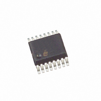
EL9110IUZ Intersil, EL9110IUZ Datasheet - Page 3

EL9110IUZ
Manufacturer Part Number
EL9110IUZ
Description
IC RECEIVR/EQUALIZER DIFF 16QSOP
Manufacturer
Intersil
Type
Receiverr
Datasheet
1.EL9110IUZ.pdf
(10 pages)
Specifications of EL9110IUZ
Number Of Drivers/receivers
0/1
Protocol
Twisted-Pair
Voltage - Supply
5V
Mounting Type
Surface Mount
Package / Case
16-QSOP
Device Type
Transceiver
Driver Case Style
QSOP
No. Of Pins
16
Operating Temperature Range
-40°C To +85°C
Filter Terminals
SMD
Transceiver Type
Differential
Rohs Compliant
Yes
Current Rating
60A
Frequency
150GHz
Lead Free Status / RoHS Status
Lead free / RoHS Compliant
Available stocks
Company
Part Number
Manufacturer
Quantity
Price
Part Number:
EL9110IUZ
Manufacturer:
INTERSIL
Quantity:
20 000
Company:
Part Number:
EL9110IUZ-T7
Manufacturer:
Intersil
Quantity:
2 000
Electrical Specifications
NOTE:
Pin Descriptions
PSRR
LOGIC CONTROL PINS
V
V
I
I
1. Parts are 100% tested at +25°C. Over-temperature limits established by characterization and are not production tested.
PARAMETER
LOGICH
LOGICL
HI
LOW
PIN NUMBER
10
11
12
13
14
15
16
1
2
3
4
5
6
7
8
9
Power Supply Rejection Ratio
Logic High Level
Logic Low Level
Logic High Input Current
Logic Low Input Current
LOGIC_REF
CTRL_REF
PIN NAME
CMOUT
CMEXT
VCTRL
VGAIN
VOUT
VSA+
ENBL
VINM
VINP
VSA-
VS+
VS-
X2
0V
DESCRIPTION
3
V
SA
+ = V
Logic Input
Logic Input
Logic Input
PIN TYPE
Output
Output
Power
Power
Power
Power
A
Input
Input
Input
Input
Input
Input
+ = +5V, V
DC to 100kHz, ±5V supply
V
V
V
V
IN
IN
IN
IN
SA
Control voltage to set overall gain (0V to 1V)
-5V to output buffer
Single-ended output voltage reference to pin 10
+5V to output buffer
Reference voltage for V
Control voltage (0 to 1V) to set equalization
Positive differential input
Negative differential input
-5V to core of chip
Output of common mode voltage present at inputs
Reference voltage for all logic signals
Logic signal; low - gain = 1, high - gain = 2
0V reference for output voltage
Logic signal to enable pin; low - disabled, high - enabled
+5V to core of chip
Logic signal to enable CM range extension; active high
- V
- V
= 5V, V
= 0V, V
- = V
LOGIC
LOGIC
A
- = -5V, T
LOGIC
LOGIC
EL9110
ref for guaranteed high level
ref for guaranteed low level
= 0V
= 0V
CONDITIONS
A
= +25°C, Unless Otherwise Specified (Continued)
GAIN
and V
CTRL
PIN FUNCTION
pins
(Note 1)
1.35
MIN
TYP
60
(Note 1)
MAX
0.8
50
15
November 30, 2007
FN7305.5
UNIT
dB
µA
µA
V
V


