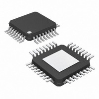
MAX3800UHJ+ Maxim Integrated Products, MAX3800UHJ+ Datasheet

MAX3800UHJ+
Specifications of MAX3800UHJ+
Related parts for MAX3800UHJ+
MAX3800UHJ+ Summary of contents
Page 1
... On-Chip Input and Output Terminations ♦ Low External Component Count ♦ Operating Temperature Range = 0°C to +85°C ♦ ESD Protection on Cable Inputs and Outputs Applications PART MAX3800UGJ MAX3800UHJ MAX3800UHJ+ *EP = exposed pad +Denotes lead-free package. EIN and Cable Driver Features Ordering Information PIN- ...
Page 2
Adaptive Equalizer and Cable Driver ABSOLUTE MAXIMUM RATINGS Supply Voltage, V ..............................................-0.5V to +6.0V CC Voltage at LOS, RMOD, and CIM...............-0. Voltage at EIN+, EIN-, DIN+, DIN- .....(V CC Current Out of EOUT+, EOUT-, DOUT+, DOUT- ................25mA ...
Page 3
AC ELECTRICAL CHARACTERISTICS (V = +3.14V to +3.46V 0°C to +85°C. Typical values are PARAMETER SYMBOL Maximum Input Data Rate CABLE DRIVER SPECIFICATIONS Random Jitter Deterministic Jitter Output Edge Speed Input Return Loss (Single-Ended) ...
Page 4
Adaptive Equalizer and Cable Driver (T = +25° +3.3V, all jitter measurements done at 3.2Gbps, 700mV cable input with ones and 100 consecutive zeros substituted. Note: Test pattern produces near worst-case jitter results. Results ...
Page 5
V = +3.3V, all jitter measurements done at 3.2Gbps, 700mV cable input with ones and 100 consecutive zeros substituted. Note: Test pattern produces near worst-case jitter results. Results will vary with pattern, unless otherwise ...
Page 6
Adaptive Equalizer and Cable Driver PIN NAME 11 Equalizer Power Supply CCE 2, 7, 10, 15, GND Ground 23, 24, 26 EIN+ Positive Equalizer Input, CML 5 EIN- Negative Equalizer Input, CML ...
Page 7
FLAT RESPONSE AMP |H(f)| CML EIN SKIN EFFECT P0WER DETECTOR COMPEN- SATION AMP LOS CML DOUT Figure 1. Functional Diagram V CC 50Ω 50Ω IN+ IN- ESD STRUCTURES GND Figure 2. CML Input Equivalent Circuit _______________________________________________________________________________________ 3.2Gbps Adaptive Equalizer ...
Page 8
Adaptive Equalizer and Cable Driver CML, see Maxim application note HFAN-1.0, Interfacing Between CML, PECL, and LVDS. Flat Response and Skin-Effect Compensation Amplifiers The buffered input waveform is fed equally to two amplifiers—the flat response amplifier and the skin- ...
Page 9
Single-Ended Operation For single-ended operation of the cable driver or equal- izer, connect the unused input to ground through a series combination of a capacitor (of equal value to other AC-coupling capacitors) and a 50Ω resistor. Note that the MAX3800 ...
Page 10
Adaptive Equalizer and Cable Driver (The package drawing(s) in this data sheet may not reflect the most current specifications. For the latest package outline information go to www.maxim-ic.com/packages.) 10 ______________________________________________________________________________________ Package Information ...
Page 11
For the latest package outline information go to www.maxim-ic.com/packages.) ______________________________________________________________________________________ 3.2Gbps Adaptive Equalizer and Cable Driver Package Information (continued) 11 ...
Page 12
Adaptive Equalizer and Cable Driver (The package drawing(s) in this data sheet may not reflect the most current specifications. For the latest package outline information go to www.maxim-ic.com/packages.) 12 ______________________________________________________________________________________ Package Information (continued) PACKAGE OUTLINE, 32L TQFP, 5x5x1.0mm, EP ...
Page 13
... Maxim cannot assume responsibility for use of any circuitry other than circuitry entirely embodied in a Maxim product. No circuit patent licenses are implied. Maxim reserves the right to change the circuitry and specifications without notice at any time. Maxim Integrated Products, 120 San Gabriel Drive, Sunnyvale, CA 94086 408-737-7600 ____________________ 13 © 2005 Maxim Integrated Products 3 ...


