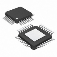
MAX3800UHJ+ Maxim Integrated Products, MAX3800UHJ+ Datasheet - Page 8

MAX3800UHJ+
Manufacturer Part Number
MAX3800UHJ+
Description
IC EQUALIZER DRVR 3.2GBPS 32TQFP
Manufacturer
Maxim Integrated Products
Type
Driverr
Datasheet
1.MAX3800UHJ.pdf
(13 pages)
Specifications of MAX3800UHJ+
Number Of Drivers/receivers
1/0
Voltage - Supply
3.14 V ~ 3.46 V
Mounting Type
Surface Mount
Package / Case
32-TQFP Exposed Pad, 32-eTQFP, 32-HTQFP, 32-VQFP
Lead Free Status / RoHS Status
Lead free / RoHS Compliant
Protocol
-
CML, see Maxim application note HFAN-1.0, Interfacing
Between CML, PECL, and LVDS.
The buffered input waveform is fed equally to two
amplifiers—the flat response amplifier and the skin-
effect compensation amplifier. The flat response ampli-
fier has a constant gain over the entire frequency range
of the device, and the skin-effect compensation amplifi-
er has a gain characteristic that approximates the
inverse of the skin-effect attenuation inherent in copper
cable. The skin-effect attenuation, in dB per unit length,
is proportional to the square root of the frequency. The
output currents from the two amplifiers are supplied to
the current-steering network. Note that when LOS
asserts low, equalization is minimized.
The function of the current-steering network is to com-
bine adjustable quantities of the output currents from
the flat response and skin-effect compensation ampli-
fiers to achieve a desired current ratio. The ratio adjust-
ment is controlled by the dual power-detector feedback
loop.
The current-steering network is implemented with a pair
of variable attenuators that feed into a current-summing
node. The variable attenuators are used to attenuate
the output currents of the flat response and skin-effect
compensation amplifiers under control of the dual
power-detector feedback loop. The outputs of the two
attenuators are combined at the summing node and
then fed to the output limiting amplifier and the feed-
back loop.
The output of the current-steering network is applied to
the inputs of two frequency-specific power detectors.
One of the power detectors is tuned to 200MHz and the
other is tuned to 600MHz. The outputs of the two power
detectors are applied to the inverting (200MHz power
detector) and noninverting (600MHz power detector)
inputs of the differential loop amplifier. The differential
outputs of the loop amplifier control the variable attenu-
ators in the current-steering network.
3.2Gbps Adaptive Equalizer
and Cable Driver
8
_______________________________________________________________________________________
Dual Power-Detector Feedback Loop
Flat Response and Skin-Effect
Current-Steering Network
Compensation Amplifiers
The output limiting amplifier amplifies the signal from
the current-steering network to achieve the specified
output voltage swing.
Refer to Maxim application note HFDN-10.0, Equalizing
Gigabit Copper Cable Links with the MAX3800 (avail-
able at www.maxim-ic.com) for additional applications
information.
The cable driver output amplitude can be adjusted by
connecting a resistor with a value from 10kΩ to 20kΩ
between the RMOD pin and ground. The exact output
amplitude of the driver for a given value of RMOD resis-
tance is dependent on a number of factors. Refer to the
Typical Operating Characteristics “Cable Driver Output
Voltage vs. RMOD” for typical values.
The differential CIM output current is directly propor-
tional to the output current of the loop amplifier (which
controls the current-steering network—see Detailed
Description). This is an analog current output that indi-
cates the amount of equalization that is being applied.
A convenient way to monitor the CIM current is to con-
nect a 100kΩ resistor from each of the CIM outputs to
ground, and then measure the voltage at the CIM pins.
The amount of equalization (and thus the CIM output
level) is affected by various factors, including cable
type, cable length, signal bandwidth, etc. Refer to the
Typical Operating Characteristics “CIM Voltage vs.
Cable Length” for typical values under specific condi-
tions.
Loss-of-signal is indicated by the LOS output. A low
level on LOS indicates that the equalizer input signal
power has dropped below a threshold. The LOS output
indicates a loss of signal. When the equalizer no longer
detects a signal from the channel, the LOS output goes
low. When there is sufficient input voltage to the chan-
nel (typically greater that 650mV), LOS is high. The LOS
output is suitable for indicating problems with the trans-
mission link caused by, for example, a broken cable, a
defective driver, or a lost connection to the equalizer.
Applications Information
Cable Integrity Monitor (CIM)
Loss-of-Signal (
Output Limiting Amplifier
Selecting RMOD
L L O O S S ) Output


