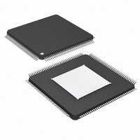
DS26303LN-120+ Maxim Integrated Products, DS26303LN-120+ Datasheet - Page 4

DS26303LN-120+
Manufacturer Part Number
DS26303LN-120+
Description
IC LIU E1/T1/J1 3.3V 144-ELQFP
Manufacturer
Maxim Integrated Products
Type
Line Interface Units (LIUs)r
Datasheet
1.DS26303L-120.pdf
(101 pages)
Specifications of DS26303LN-120+
Number Of Drivers/receivers
8/8
Protocol
T1/E1/J1
Voltage - Supply
3.135 V ~ 3.465 V
Mounting Type
Surface Mount
Package / Case
144-LQFP Exposed Pad, 144-eLQFP, 144-HLQFP
Maximum Operating Temperature
+ 85 C
Mounting Style
SMD/SMT
Minimum Operating Temperature
- 40 C
Lead Free Status / RoHS Status
Lead free / RoHS Compliant
DS26303: 3.3V, T1/E1/J1, Short-Haul, Octal Line Interface Unit
LIST OF FIGURES
Figure 3-1. Block Diagram ........................................................................................................................................... 9
Figure 3-2. Receive Logic Detail................................................................................................................................ 10
Figure 3-3. Transmit Logic Detail............................................................................................................................... 10
Figure 4-1. 144-Pin eLQFP Pin Assignment ............................................................................................................. 19
Figure 4-2. Serial Port Operation for Write Access ................................................................................................... 21
Figure 4-3. Serial Port Operation for Read Access with CLKE = 0 ........................................................................... 21
Figure 4-4. Serial Port Operation for Read Access with CLKE = 1 ........................................................................... 22
Figure 4-5. Interrupt Handling Flow Diagram ............................................................................................................ 23
Figure 6-1. Prescaler PLL and Clock Generator ....................................................................................................... 54
Figure 6-2. T1 Transmit Pulse Templates ................................................................................................................. 56
Figure 6-3. E1 Transmit Pulse Templates ................................................................................................................. 57
Figure 6-4. LIU Front-End.......................................................................................................................................... 58
Figure 6-5. HPS Logic ............................................................................................................................................... 63
Figure 6-6. HPS Block Diagram................................................................................................................................. 63
Figure 6-7. Jitter Attenuation ..................................................................................................................................... 64
Figure 6-8. Analog Loopback..................................................................................................................................... 65
Figure 6-9. Digital Loopback...................................................................................................................................... 66
Figure 6-10. Remote Loopback ................................................................................................................................. 66
Figure 6-11. Dual Loopback ...................................................................................................................................... 67
Figure 6-12. PRBS Synchronization State Diagram.................................................................................................. 70
Figure 6-13. Repetitive Pattern Synchronization State Diagram............................................................................... 71
Figure 7-1. JTAG Functional Block Diagram ............................................................................................................. 72
Figure 7-2. TAP Controller State Diagram................................................................................................................. 75
Figure 10-1. Intel Nonmuxed Read Cycle ................................................................................................................. 82
Figure 10-2. Intel Mux Read Cycle ............................................................................................................................ 83
Figure 10-3. Intel Nonmux Write Cycle...................................................................................................................... 85
Figure 10-4. Intel Mux Write Cycle ............................................................................................................................ 86
Figure 10-5. Motorola Nonmux Read Cycle .............................................................................................................. 88
Figure 10-6. Motorola Mux Read Cycle..................................................................................................................... 89
Figure 10-7. Motorola Nonmux Write Cycle .............................................................................................................. 91
Figure 10-8. Motorola Mux Write Cycle ..................................................................................................................... 92
Figure 10-9. Serial Bus Timing Write Operation........................................................................................................ 93
Figure 10-10. Serial Bus Timing Read Operation with CLKE = 0.............................................................................. 93
Figure 10-11. Serial Bus Timing Read Operation with CLKE = 1.............................................................................. 93
Figure 10-12. Transmitter Systems Timing ............................................................................................................... 94
Figure 10-13. Receiver Systems Timing ................................................................................................................... 95
Figure 10-14. JTAG Timing ....................................................................................................................................... 96
4 of 101


