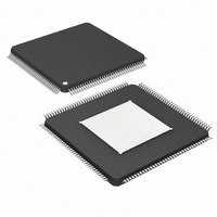
DS26303LN-120+ Maxim Integrated Products, DS26303LN-120+ Datasheet - Page 73

DS26303LN-120+
Manufacturer Part Number
DS26303LN-120+
Description
IC LIU E1/T1/J1 3.3V 144-ELQFP
Manufacturer
Maxim Integrated Products
Type
Line Interface Units (LIUs)r
Datasheet
1.DS26303L-120.pdf
(101 pages)
Specifications of DS26303LN-120+
Number Of Drivers/receivers
8/8
Protocol
T1/E1/J1
Voltage - Supply
3.135 V ~ 3.465 V
Mounting Type
Surface Mount
Package / Case
144-LQFP Exposed Pad, 144-eLQFP, 144-HLQFP
Maximum Operating Temperature
+ 85 C
Mounting Style
SMD/SMT
Minimum Operating Temperature
- 40 C
Lead Free Status / RoHS Status
Lead free / RoHS Compliant
7.1 TAP Controller State Machine
The TAP controller is a finite state machine that responds to the logic level at JTMS on the rising edge of TCLK.
The state diagram is shown in
7.1.1
Upon power-up, the TAP controller will be in the Test-Logic-Reset state. The instruction register will contain the
IDCODE instruction. All system logic of the device will operate normally. This state is automatically entered during
power-up. This state is entered from any state if the JTMS is held high for at least 5 clocks.
7.1.2
The Run-Test-Idle is used between scan operations or during specific tests. The instruction register and test
registers will remain idle. The controller remains in this state when JTMS is held low. When the JTMS is high and
rising edge of TCLK is applied the controller moves to the Select-DR-Scan state.
7.1.3
All test registers retain their previous state. With JTMS LOW, a rising edge of TCLK moves the controller into the
Capture-DR state and will initiate a scan sequence. JTMS HIGH during a rising edge on TCLK moves the controller
to the Select-IR-Scan state.
7.1.4
Data can be parallel-loaded into the test-data registers if the current instruction is EXTEST or SAMPLE/PRELOAD.
If the instruction does not call for a parallel load or the selected register does not allow parallel loads, the test
register will remain at its current value. On the rising edge of TCLK, the controller will go to the Shift-DR state if
JTMS is LOW or it will go to the Exit1-DR state if JTMS is HIGH.
7.1.5 Shift-DR
The test-data register selected by the current instruction will be connected between JTDI and JTDO and will shift
data one stage towards its serial output on each rising edge of TCLK. If a test register selected by the current
instruction is not placed in the serial path, it will maintain its previous state. When the TAP controller is in this state
and a rising edge of TCLK is applied, the controller enters the Exit1-DR state if JTMS is high or remains in Shift-DR
state if JTMS is low.
7.1.6 Exit1-DR
While in this state, a rising edge on TCLK will put the controller in the Update-DR state, which terminates the
scanning process, if JTMS is HIGH. A rising edge on TCLK with JTMS LOW will put the controller in the Pause-DR
state.
7.1.7 Pause-DR
Shifting of the test registers is halted while in this state. All test registers selected by the current instruction will
retain their previous state. The controller will remain in this state while JTMS is LOW. A rising edge on TCLK with
JTMS HIGH will put the controller in the Exit2-DR state.
7.1.8 Exit2-DR
A rising edge on TCLK with JTMS HIGH while in this state will put the controller in the Update-DR state and
terminate the scanning process. A rising edge on TCLK with JTMS LOW will enter the Shift-DR state.
7.1.9
A falling edge on TCLK while in the Update-DR state will latch the data from the shift register path of the test
registers into the data output latches. This prevents changes at the parallel output due to changes in the shift
register.
Test-Logic-Reset
Run-Test-Idle
Select-DR-Scan
Capture-DR
Update-DR
Figure 7-2.
DS26303: 3.3V, T1/E1/J1, Short-Haul, Octal Line Interface Unit
73 of 101


