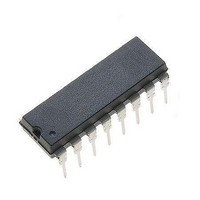
ML4802CP Fairchild Semiconductor, ML4802CP Datasheet

ML4802CP
Specifications of ML4802CP
Available stocks
Related parts for ML4802CP
ML4802CP Summary of contents
Page 1
PFC/PWM Controller Combo with Green Mode GENERAL DESCRIPTION The ML 4802 is a controller for power factor corrected, switched mode power supplies that offers Green Mode operation and reduced start-up and operating currents. Green Mode is an efficiency improving circuit ...
Page 2
ML4802 PIN CONFIGURATION PIN DESCRIPTION PIN NAME FUNCTION 1 IEAO PFC current error amplifier output 2 IAC PFC gain control reference input 3 ISENSE Current sense input to the PFC current limit comparator 4 VRMS Input for PFC RMS line ...
Page 3
ABSOLUTE MAXIMUM RATINGS Absolute maximum ratings are those values beyond which the device could be permanently damaged. Absolute maximum ratings are stress ratings only and functional device operation is not implied. VCC ........................................................................... 18V ISENSE Voltage ................................................ – ...
Page 4
ML4802 ELECTRICAL CHARACTERISTICS (Continued) SYMBOL PARAMETER OVP COMPARATOR Threshold Voltage Hysteresis PFC ILIMIT COMPARATOR Threshold Voltage PFC ILIMIT Threshold - Gain Modulator Output Delay to Output DC ILIMIT COMPARATOR Threshold Voltage Input Bias Current Delay to Output VIN OK COMPARATOR ...
Page 5
ELECTRICAL CHARACTERISTICS (Continued) SYMBOL PARAMETER REFERENCE Output Voltage Line Regulation Load Regulation Temperature Stability Total Variation Long Term Stability PFC Minimum Duty Cycle Maximum Duty Cycle Output Low Voltage Output High Voltage Rise/Fall Time PWM DC Duty Cycle Range VOL ...
Page 6
ML4802 FUNCTIONAL DESCRIPTION The ML4802 consists of a combined average-current- controlled, continuous boost Power Factor Corrector (PFC) front end and a synchronized Pulse Width Modulator (PWM) back end distinguished from earlier combo controllers by its unique Green Mode ...
Page 7
FUNCTIONAL DESCRIPTION (Continued instantaneous basis, an increase in VOUT above its programmed value will cause the error voltage presented to VDC to decrease. This will shut off PWMOUT to keep the loop in regulation. If the output voltage ...
Page 8
ML4802 FUNCTIONAL DESCRIPTION (Continued) control loop for the converter, which in turn drives a current error amplifier and switching output driver. The second requirement is met by using the rectified AC line voltage to modulate the output of the voltage ...
Page 9
FUNCTIONAL DESCRIPTION (Continued) The output of the gain modulator is a current signal, in the form of a full wave rectified sinusoid at twice the line frequency. This current is applied to the virtual-ground (negative) input of the current error ...
Page 10
ML4802 FUNCTIONAL DESCRIPTION (Continued) The major concern when compensating the ML4802's voltage loop error amplifier is that the current amplifier compensation is chosen to optimize frequency response while maintaining good stability. This leads to the following rules of thumb: the ...
Page 11
FUNCTIONAL DESCRIPTION (Continued) PWM SECTION Pulse Width Modulator The PWM section of the ML4802 is straightforward, but there are several points which should be noted. Foremost among these is its inherent synchronization to the PFC section of the device, from ...
Page 12
ML4802 FUNCTIONAL DESCRIPTION (Continued) In the case of leading edge modulation, the switch is turned OFF right at the leading edge of the system clock. When the modulating ramp reaches the level of the error amplifier output voltage, the switch ...
Page 13
Figure 7. 100W Power Factor Corrected Power Supply REV. 1.0.1 12/12/2000 ML4802 13 ...
Page 14
ML4802 PHYSICAL DIMENSIONS inches (millimeters) 16 PIN 0.02 MIN (0.50 MIN) (4 PLACES) 0.170 MAX (4.32 MAX) 0.125 MIN (3.18 MIN 0.017 - 0.027 (0.43 - 0.69) (4 PLACES) 0.055 - 0.061 (1.40 - 1.55) ...
Page 15
... ORDERING INFORMATION PART NUMBER ML4802CP ML4802CS ML4802IP ML4802IS DISCLAIMER FAIRCHILD SEMICONDUCTOR RESERVES THE RIGHT TO MAKE CHANGES WITHOUT FURTHER NOTICE TO ANY PRODUCTS HEREIN TO IMPROVE RELIABILITY, FUNCTION OR DESIGN. FAIRCHILD DOES NOT ASSUME ANY LIABILITY ARISING OUT OF THE APPLICATION OR USE OF ANY PRODUCT OR CIRCUIT DESCRIBED HEREIN; ...


