VIPER20A STMicroelectronics, VIPER20A Datasheet
VIPER20A
Specifications of VIPER20A
Available stocks


Related parts for VIPER20A


VIPER20A Summary of contents
Page 1
... INTEGRATED START-UP SUPPLY AVALANCHE RUGGED OVERTEMPERATURE PROTECTION LOW STAND-BY CURRENT ADJUSTABLE CURRENT LIMITATION BLOCK DIAGRAM VDD ERROR AMPLIFIER July 2002 - VIPer20A/ASP/ADIP SMPS PRIMARY I. DS(on PENTAWATT HV 10 PowerSO-10™ DESCRIPTION VIPer20/20A, Technology, combines on the same silicon chip a state-of-the-art PWM circuit together with an optimized high voltage avalanche rugged Vertical Power MOSFET (620V or 700V / 0 ...
Page 2
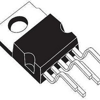
... When mounted using the minimum recommended pad size on FR-4 board. (#) On multylayer PCB. CONNECTION DIAGRAMS (Top View) PENTAWATT HV PENTAWATT HV (022Y) CURRENT AND VOLTAGE CONVENTIONS OSC VIPer20/SP/DIP - VIPer20A/ASP/ADIP Parameter =25 to 125° max; < 1%) j PENTAWATT PowerSO-10™ (*) Max 2.0 70 PowerSO-10™ VDD DRAIN ...
Page 3
... VIPer20/SP/DIP - VIPer20A/ASP/ADIP ORDERING NUMBERS PENTAWATT HV PENTAWATT HV (022Y) VIPer20 VIPer20 (022Y) VIPer20A VIPer20A (022Y) PINS FUNCTIONAL DESCRIPTION DRAIN PIN: Integrated Power MOSFET drain pin. It provides internal bias current during start-up via an integrated high voltage current source which is switched off during normal operation. The device ...
Page 4
... Parameter max; < 1%) (see fig.12) ) (see fig.12) =25° =13V, unless otherwise specified Test Conditions I =1mA; V =0V D COMP for VIPer20/SP/DIP for VIPer20A/ASP/ADIP (see fig.5) V =0V; T =125°C COMP j V =620V for VIPer20/SP/DIP DS V =700V for VIPer20A/ASP/ADIP DS I =0.4A D for VIPer20/SP/DIP for VIPer20A/ASP/ADIP I =0.4A ...
Page 5
... VIPer20/SP/DIP - VIPer20A/ASP/ADIP ELECTRICAL CHARACTERISTICS (continued) OSCILLATOR SECTION Symbol Parameter Oscillator Frequency F SW Total Variation V Oscillator Peak Voltage OSCih V Oscillator Valley Voltage OSCil ERROR AMPLIFIER SECTION Symbol Parameter V V Regulation Point DDreg DD V Total Variation DDreg G Unity Gain Bandwidth BW A Open Loop Voltage Gain ...
Page 6
... Figure 3: Transition Time I D 10% Ipeak Figure 5: Breakdown Voltage Vs. Temperature 1.15 BV DSS (Normalized) 1.1 1. Temperature (°C) VIPer20/SP/DIP - VIPer20A/ASP/ADIP Figure 2: Undervoltage Lockout DD0 DDch FC00150 Figure 4: Shut Down Action VOSC VCOMP t VCOMPth ID t FC00160 Figure 6: Typical Frequency Variation FC00180 1 (%) ...
Page 7
... VIPer20/SP/DIP - VIPer20A/ASP/ADIP Figure 7: Start-Up Waveforms Figure 8: Overtemperature Protection T tsc T -T tsd hyst V V ddon V ddoff V comp 7/ SC10191 ...
Page 8
... Figure 9: Oscillator VDD Rt OSC 22nF 15nF 1,000 Ct = 1.5 nF 500 300 200 100 VIPer20/SP/DIP - VIPer20A/ASP/ADIP For R >1.2K t and C 15nF CLK SW FC00050 Forbidden area 880 Ct(nF) = Fsw(kHz) Forbidden area 40kHz Oscillator frequency vs Rt and 2 4 40KHz SW 2.3 550 ----------- - --------------------- - 1 – 150 – Fsw FC00030 ...
Page 9
... VIPer20/SP/DIP - VIPer20A/ASP/ADIP Figure 10: Error Amplifier Frequency Response 60 RCOMP = + RCOMP = 270k 40 RCOMP = 82k RCOMP = 27k RCOMP = 12k 20 0 (20) 0.001 Figure 11: Error Amplifier Phase Response 200 150 100 50 0 (50) 0.001 9/25 0.01 0 Frequency (kHz) 0.01 0 Frequency (kHz) FC00200 100 1,000 FC00210 RCOMP = + RCOMP = 270k ...
Page 10
... Figure 12: Avalanche Test Circuit 2 VDD - 1 OSC 13V + C1 U1 BT2 VIPer20 47uF 12V 16V R2 1k VIPer20/SP/DIP - VIPer20A/ASP/ADIP L1 1mH 3 DRAIN STHV102FI in parallel R1 47 COMP SOURCE 100 BT1 0 to 20V GENERATOR INPUT 500us PULSE FC00196 10/25 1 ...
Page 11
... Figure 13: Off Line Power Supply With Auxiliary Supply Feedback F1 TR2 OSC C5 Figure 14: Off Line Power Supply With Optocoupler Feedback VIPer20/SP/DIP - VIPer20A/ASP/ADIP BR1 TR1 VDD DRAIN - VIPer20 + 13V COMP SOURCE C6 C11 AIN - V IP er20 + 13V C11 +Vcc C7 C9 GND C10 FC00401 C10 ...
Page 12
... P by STBY STBY P 2 Where the primary inductance of the transformer. P VIPer20/SP/DIP - VIPer20A/ASP/ADIP F is the normal switching frequency the minimum controllable current, STBY corresponding to the minimum on time that the device is able to provide in normal operation. This current can be computed as STBY -------------------------------- = ...
Page 13
... C VDD V DDhyst Figure 15: Behavior of the high voltage current source at start-up VDD VDDon VDDoff t Auxiliary primary VIPer20/SP/DIP - VIPer20A/ASP/ADIP where the consumption current on the V DD when switching. Refer to specified I values the start up time of the converter when the SS device begins to switch. Worst case is generally at full load ...
Page 14
... FC00431 VIPer20/SP/DIP - VIPer20A/ASP/ADIP achieve different compensation laws. A capacitor will provide an integrator function, thus eliminating the DC static error, and a resistance in series leads to a flat gain at higher frequency, insuring a correct phase margin. This configuration is illustrated in figure 18. As shown in figure 18 an additional noise filtering capacitor of 2 ...
Page 15
... FC00451 Figure 20: External Clock Synchronization VDD OSC 13V 10 k VIPer20/SP/DIP - VIPer20A/ASP/ADIP OVER-TEMPERATURE PROTECTION: Over-temperature protection is based on chip temperature sensing. The minimum junction temperature at which over-temperature cut-out occurs is 140ºC while the typical value is 170ºC. The device is automatically restarted when the junction temperature decreases to the restart temperature threshold that is typically 40º ...
Page 16
... The VIPer may be submitted to electrical over stress caused by violent input voltage surges or lightning. Following the enclosed Considerations chapter rules is the most of the time sufficient to prevent catastrophic damages, however in some cases the voltage surges coupled through the transformer auxiliary winding VIPer20/SP/DIP - VIPer20A/ASP/ADIP R1 (Optional) R2 39R VDD DRAIN - OSC + ...
Page 17
... This avoids radiated EMC noises, conducted EMC noises by magnetic coupling, and provides a better efficiency by eliminating parasitic inductances, especially on secondary side. VIPer20/SP/DIP - VIPer20A/ASP/ADIP VDD DRAIN - ...
Page 18
... F (*) 1.20 H 13.80 H (*) 13. 1.20 L (*) 0.80 0º (*) 2º (*) Muar only POA P013P 0. VIPer20/SP/DIP - VIPer20A/ASP/ADIP mm. TYP MAX. MIN. 3.65 0.132 3.6 0.134 0.10 0.000 0.60 0.016 0.53 0.014 0.55 0.013 0.32 0.009 9.60 0.370 7.60 0.291 9.50 0.366 7.60 0.283 7.50 0.287 6.10 ...
Page 19
... H1 H2 10. 15.60 L1 14.60 L2 21.20 L3 22.20 L5 2.60 L6 15. 2.50 M1 4.50 R 0.50 V4 Diam 3.65 VIPer20/SP/DIP - VIPer20A/ASP/ADIP inch MAX. MIN. TYP. 4.80 0.169 1.37 0.046 2.80 0.094 0.55 0.014 0.80 0.024 5.21 0.193 7.80 0.295 9.70 0.366 10.40 10.40 0.396 17.30 6.14 15.22 0.575 21 ...
Page 20
... H2 H3 10.05 L 16.42 L1 14.60 L3 20.52 L5 2.60 L6 15.10 L7 6.00 M 2.50 M1 5.00 R 0.50 V4 90° Diam. 3.70 VIPer20/SP/DIP - VIPer20A/ASP/ADIP inch MAX. MIN. TYP. 4.80 0.169 1.37 0.046 2.80 0.094 0.55 0.014 0.80 0.024 5.21 0.193 7.80 0.295 9.70 0.366 10.40 10.40 0.396 17.42 ...
Page 21
... Plastic DIP-8 MECHANICAL DATA DIM. MIN 0.38 A2 2.92 b 0.36 b2 1.14 c 0.20 D 9.02 E 7. 2.92 Package Weight VIPer20/SP/DIP - VIPer20A/ASP/ADIP mm. TYP MAX. 5.33 3.30 4.95 0.46 0.56 1.52 1.78 0.25 0.36 9.27 10.16 7.87 8.26 6.35 7.11 2.54 7.62 10.92 3.30 3.81 Gr. 470 P001 ...
Page 22
... Hole Diameter D (± 0.1/-0) Hole Diameter D1 (min) Hole Position F (± 0.05) Compartment Depth K (max) Hole Spacing P1 (± 0.1) All dimensions are in mm. VIPer20/SP/DIP - VIPer20A/ASP/ADIP TUBE SHIPMENT (no suffix) CASABLANCA All dimensions are in mm. Base Q.ty Bulk Q.ty Tube length (± 0.5) A Casablanca 50 1000 ...
Page 23
... VIPer20/SP/DIP - VIPer20A/ASP/ADIP PENTAWATT HV TUBE SHIPMENT (no suffix 23/25 Base Q.ty Bulk Q.ty Tube length (± 0. (± 0.1) C All dimensions are in mm. 50 1000 532 18 33 ...
Page 24
... DIP-8 TUBE SHIPMENT (no suffix Base Q.ty Bulk Q.ty Tube length (± 0. (± 0.1) All dimensions are in mm. VIPer20/SP/DIP - VIPer20A/ASP/ADIP 20 1000 532 8.4 11.2 0.8 24/25 1 ...
Page 25
... VIPer20/SP/DIP - VIPer20A/ASP/ADIP Information furnished is believed to be accurate and reliable. However, STMicroelectronics assumes no responsibility for the consequences of use of such information nor for any infringement of patents or other rights of third parties which may results from its use. No license is granted by implication or otherwise under any patent or patent rights of STMicroelectronics. Specifications mentioned in this publication are subject to change without notice ...