1003 Murata Power Solutions Inc, 1003 Datasheet - Page 2
1003
Manufacturer Part Number
1003
Description
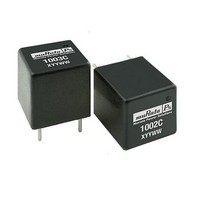
Transformers PULSE XFRMR
Manufacturer
Murata Power Solutions Inc
Type
Pulse Transformersr
Datasheet
1.1001.pdf
(2 pages)
Specifications of 1003
Mounting Style
Through Hole
Dimensions
15.06 mm L x 15.06 mm H
Product
PCB Mount Transformers
Height
15.06 mm
Length
15.06 mm
Number Of Outputs
1
Operating Temperature Range
0 C to + 70 C
Turns Ratio
2:1:1
Lead Free Status / Rohs Status
Lead free / RoHS Compliant
Available stocks
Company
Part Number
Manufacturer
Quantity
Price
Company:

Part Number:
1003
Manufacturer:
TOSHIBA
Quantity:
155 116
Part Number:
1003010168
Manufacturer:
MOLEX
Quantity:
20 000
Part Number:
1003010325
Manufacturer:
MOLEX
Quantity:
20 000
Part Number:
1003010343
Manufacturer:
MOLEX
Quantity:
20 000
Part Number:
1003010353
Manufacturer:
MOLEX
Quantity:
20 000
Part Number:
1003010363
Manufacturer:
MOLEX
Quantity:
20 000


Murata Power Solutions, Inc.
11 Cabot Boulevard, Mansfield, MA 02048-1151 U.S.A.
Tel: (508) 339-3000 (800) 233-2765 Fax: (508) 339-6356
www.murata-ps.com email: sales@murata-ps.com
Murata Power Solutions, Inc. makes no representation that the use of its products in the circuits described herein, or the use of other
technical information contained herein, will not infringe upon existing or future patent rights. The descriptions contained herein do not imply
the granting of licenses to make, use, or sell equipment constructed in accordance therewith. Specifications are subject to change without
notice.
TECHNICAL NOTES
ISOLATION
‘Hi Pot Test’, ‘Flash Tested’, ‘Withstand Voltage’, ‘Proof Voltage’, ‘Dielectric Withstand Voltage’ & ‘Isola-
tion Test Voltage’ are all terms that relate to the same thing, a test voltage, applied for a specified time,
across a component designed to provide electrical isolation, to verify the integrity of that isolation.
All products in this series are 100% production tested at their stated isolation voltage.
A question commonly asked is, “What is the continuous voltage that can be applied across the part in
normal operation?”
For a part holding no specific agency approvals both input and output should normally be maintained
within SELV limits i.e. less than 42.4V peak, or 60VDC. The isolation test voltage represents a measure
of immunity to transient voltages and the part should never be used as an element of a safety isolation
system. The part could be expected to function correctly with several hundred volts offset applied
continuously across the isolation barrier; but then the circuitry on both sides of the barrier must be
regarded as operating at an unsafe voltage and further isolation/insulation systems must form a barrier
between these circuits and any user-accessible circuitry according to safety standard requirements.
PIN CONNECTIONS
www.murata-ps.com
A
B
C
2
4
6
2
4
6
VOLTAGE
2
6
Sec
(TOP VIEW)
S2
Sec
Pri
Pri
S1
Pri
1
3
5
1
3
5
1
5
© 2008 Murata Power Solutions, Inc.
ISO 9001 REGISTERED
MECHANICAL DIMENSIONS
All dimensions in mm (inches). Package weight: 8.0g Typ.
5.08 (0.20)
1
(0.807)
20.5
1003C
15.06 (0.593)
YYWW
10.16 (0.40)
USA:
Canada: Toronto, Tel: (866) 740 1232, email: toronto@murata-ps.com
UK:
France:
Germany: München, Tel: +49 (0)89-544334-0, email: ped.munich@murata-ps.com
Japan:
China:
(0.620±0.02)
Mansfield (MA), Tel: (800) 233 2765, email: sales@murata-ps.com
Milton Keynes, Tel: +44 (0)1908 615232, email: mk@murata-ps.com
Montigny Le Bretonneux, Tel: +33 (0)1 34 60 01 01, email: france@murata-ps.com
Tokyo, Tel: 3-3779-1031, email: sales_tokyo@murata-ps.com
Osaka, Tel: 6-6354-2025, email: sales_osaka@murata-ps.com
Website: www.murata-ps.jp
Shanghai, Tel: +86 215 027 3678, email: shanghai@murata-ps.com
Guangzhou, Tel: +86 208 221 8066, email: guangzhou@murata-ps.com
15.75±0.50
5.08 (0.20)
Ø0.71±0.05
(Ø0.028±0.002)
(0.593)
15.06
REPEATED HIGH-VOLTAGE ISOLATION TESTING
It is well known that repeated high-voltage isolation testing of a barrier
component can actually degrade isolation capability, to a lesser or great-
er degree depending on materials, construction and environment. While
parts can be expected to withstand several times the stated test voltage,
the isolation capability does depend on the insulative materials used.
Such materials are susceptible to chemical degradation when subject
to very high applied voltages. We therefore strongly advise against
repeated high voltage isolation testing, but if it is absolutely required,
that the voltage be reduced by 20% from specified test voltage.
This consideration equally applies to agency recognized parts rated for
better than functional isolation where wire enamel insulation is always
supplemented by a further insulation system of physical spacing or
barriers.
Technical enquiries - email: mk@murata-ps.com, tel:
2
(0.807)
20.5
1001C
15.06 (0.593)
YYWW
10.16 (0.40)
1000 Series
KMP_1000C_B02 Page 2 of 2
Pulse Transformers
(0.620±0.02)
15.75±0.50
+44 (0)1908 615232
10.16 (0.40)
Ø0.71±0.05
(Ø0.028±0.002)
(0.593)
15.06
Related parts for 1003
Image
Part Number
Description
Manufacturer
Datasheet
Request
R

Part Number:
Description:
Power Inductors 100uH 0.24A SMT Ind Mini Toroidal
Manufacturer:
Murata Power Solutions Inc

Part Number:
Description:
Power Inductors 100uH 0.35A SMT Ind Drum Low Profile
Manufacturer:
Murata Power Solutions Inc

Part Number:
Description:
Power Inductors 100uH 0.23A SMT Ind Drum Low Profile
Manufacturer:
Murata Power Solutions Inc

Part Number:
Description:
Power Inductors 47uH 8.3A 6MHz Radial PCB Mounting
Manufacturer:
Murata Power Solutions Inc
Datasheet:
Part Number:
Description:
Power Inductors BOBBIN TYPE 680uH
Manufacturer:
Murata Power Solutions Inc
Datasheet:

Part Number:
Description:
Power Inductors Mini Radial 68mH
Manufacturer:
Murata Power Solutions Inc
Datasheet:

Part Number:
Description:
Power Inductors AXIAL LEAD 100uH
Manufacturer:
Murata Power Solutions Inc

Part Number:
Description:
Ind 100uH, 0.28A SM Drum Shielded
Manufacturer:
Murata Power Solutions Inc
Datasheet:


Part Number:
Description:
DC/DC Converters & Regulators 48Vin 5Vout 20A neg polarity TH
Manufacturer:
Murata Power Solutions Inc
Datasheet:

Part Number:
Description:
Transformers 5Vin 5Vout 200mA 4000Vdc 1:1.33 turn
Manufacturer:
Murata Power Solutions Inc
Datasheet:

Part Number:
Description:
POWER SUPPLY
Manufacturer:
Murata Power Solutions Inc
Datasheet:

Part Number:
Description:
DPM LED MINI 2VDC 3.5DIG LP RED
Manufacturer:
Murata Power Solutions Inc
Datasheet:

Part Number:
Description:
CONV DC/DC 1W 5VIN 5VOUT SIP SGL
Manufacturer:
Murata Power Solutions Inc
Datasheet:

Part Number:
Description:
CONV DC/DC 1W 5VIN 3.3V SIP SGL
Manufacturer:
Murata Power Solutions Inc
Datasheet: