HS7A-DMC7902 IDEC, HS7A-DMC7902 Datasheet - Page 4
HS7A-DMC7902
Manufacturer Part Number
HS7A-DMC7902
Description
NON-CONTACT SAFETY INTERLOCK SWITCH, DPST-NC, 24VDC
Manufacturer
IDEC
Datasheet
1.HS7A-DMC5902.pdf
(7 pages)
Specifications of HS7A-DMC7902
Contact Configuration
DPST-NC
Contact Voltage Dc Max
24V
Contact Current Dc Max
100mA


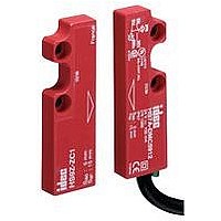
HS7A-DMC Non-contact Interlock Switches
•
•
•
•
•
•
•
Operating Direction
Precautions for Installation
Tightening Torque
688
When installing on a ferromagnet
In order to avoid electric shock or fire, turn power off before instal-
lation, removal, wire connection, maintenance, or inspection of
the non-contact interlock switch .
Safety category 4 (EN954-1) can be achieved by combining the
HS7A non-contact interlock switch and HR1S safety relay module
(monitor the dual contacts using the safety relay module) .
When using non-contact interlock switches, combine with a
propri etary safety relay module and confirm that the conformable
safety category and the safety category (EN954-1) required to the
machinery have been achieved .
Be sure to use the HS7A non-contact interlock switch in combina-
tion with the proprietary actuator HS9Z-ZC1 . Do not use other
actuators .
Regardless of door types, do not use the non-contact interlock
switch as a door stop . Install a mechanical door stop on the edge
of the door to protect the interlock switch against excessive force .
A shock to the door exceeding 300 m/s
a failure to the switch .
Do not store the non-contact interlock switches in a dusty, humid,
organic-gas atmosphere, or areas subject to direct sunlight .
Ferromagnet
b > 13 mm
d = 81 × 55 mm
Safety Precautions
Instructions
b
A: nonmagnetic material
1 N·m max.
A
A
∗ Safety output ON distance (Sao): 3 mm
d
Use a nonmagnetic screw.
Markings
2
(approx . 30G) may cause
Close mounting
a
a
a > 40 mm
Markings
∗
•
Precaution for Cable Wiring
Precautions for Mounting the Actuator
Operation Chart
• Contact Status
• Operation Area
HS7A-DMC59
Brown/Blue
Black/White
Do not install the actuator in the location where the human body
may come in contact . Otherwise injury may occur .
Tensile force on the cable may cause disconnection . Be sure
to secure the cable near the non-contact interlock switches .
Do not use the non-contact
interlock switch as a mechanical
stop for movable guard.
Do not use a hammer to adjust
a position of the non-contact
interlock switch.
Do not use the non-contact interlock switch in a magnetic
field of 0.3 mT or over.
Contact Closed (1)
Contact Open (0)
Transient State
0
(mm)
10
8
6
4
2
0
-2
5 (Sao) 15 (Sar)
14
(1NO+1NC)
-1
Sao: Assured operating distance where
Sar: Assured release distance where
Note: When the transfer time between the
actuator’s Sao-Sar is 500 ms or longer, the
time lag is detected as an error.
100 mm
Safety output ON area
the safety output is sure to turn on.
the safety output is sure to turn off.
0
Brown/Blue
Black/White
HS7A-DMC79
> 0.3 mT
1
1 mm
0
5 (Sao) 15 (Sar)
14
2
Dimensions: mm
(mm)
(2NO)
Related parts for HS7A-DMC7902
Image
Part Number
Description
Manufacturer
Datasheet
Request
R

Part Number:
Description:
NON-CONTACT SAFETY INTERLOCK SWITCH, SPST-NO/SPST-NC, 24VDC
Manufacturer:
IDEC
Datasheet:
Part Number:
Description:
NON-CONTACT SAFETY INTERLOCK SWITCH, SPST-NO/SPST-NC, 24VDC
Manufacturer:
IDEC
Datasheet:
Part Number:
Description:
NON-CONTACT SAFETY INTERLOCK SWITCH, DPST-NC, 24VDC
Manufacturer:
IDEC
Datasheet:

Part Number:
Description:
NON-CONTACT SAFETY INTERLOCK SWITCH, SPST-NO/DPST-NC, 24VDC
Manufacturer:
IDEC
Datasheet:
Part Number:
Description:
NON-CONTACT SAFETY INTERLOCK SWITCH, SPST-NO/DPST-NC, 24VDC
Manufacturer:
IDEC
Datasheet:
Part Number:
Description:
NON-CONTACT SAFETY INTERLOCK SWITCH, DPST-NO/SPST-NC, 24VDC
Manufacturer:
IDEC
Datasheet:
Part Number:
Description:
NON-CONTACT SAFETY INTERLOCK SWITCH, DPST-NO/SPST-NC, 24VDC
Manufacturer:
IDEC
Datasheet:

Part Number:
Description:
Cable; Between IDEC MicroSmart (port 1 or 2) and HG2F/3F/4F; 5 ft.
Manufacturer:
IDEC Corporation
Datasheet:
Part Number:
Description:
Cable; Between IDEC Micro^3C/ONC/MicroSmart (port 2) PLCs and HG2F/3F/4F; 5 ft.
Manufacturer:
IDEC Corporation
Datasheet:
Part Number:
Description:
INDICATOR INCANDESCENT LAMP, GREEN
Manufacturer:
IDEC
Datasheet:

Part Number:
Description:
LAMP, INDICATOR, INCAND, AMB
Manufacturer:
IDEC
Datasheet:
Part Number:
Description:
LAMP, INDICATOR, INCAND, GRN
Manufacturer:
IDEC
Datasheet:
Part Number:
Description:
LAMP, INDICATOR, INCAND, GRN
Manufacturer:
IDEC
Datasheet:
Part Number:
Description:
LAMP, INDICATOR, INCANDESCENT, RED
Manufacturer:
IDEC
Datasheet: