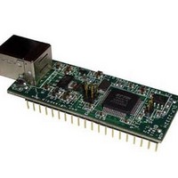
DLP-2232H DLP Design Inc, DLP-2232H Datasheet
DLP-2232H
Specifications of DLP-2232H


Related parts for DLP-2232H


DLP-2232H Summary of contents
Page 1
... The DLP-2232H is shipped from the factory in DLP-2232M compatible mode. Refer to section 2.1 for mode select jumper The DLP-2232H has the capability of being configured in a variety of industry standard serial or parallel interfaces supporting these features: • Entire USB protocol handled on the module. No USB specific firmware programming required. ...
Page 2
... USB audio and low-bandwidth video data transfer • USB hardware modems • USB wireless modems DRIVER SUPPORT: Royalty-Free Virtual COM Port (VCP) Drivers for: • Windows 2000, Server 2003, Server 2008 • Windows XP and XP 64-bit Rev. 1.1 (May 2011) 2 © DLP Design, Inc. ...
Page 3
... USB silicon. It has the capability of being configured in a variety of industry standard serial or parallel interfaces. The DLP-2232H can be configured for UART, FIFO, Fast serial interface, JTAG, SPI, I2C or bit-bang mode. In addition to these, the DLP-2232H supports a CPU interface FIFO mode and MCU host bus emulation mode. ...
Page 4
... PIN DESCRIPTIONS This section describes the operation of the DLP-2232H pins. The function of the I/O pins is determined by the configuration that is stored in the EEPROM connected to the FT2232H IC. The following table details the function of each pin for the specified mode. Note that the convention used throughout this document for active low signals is the signal name followed ...
Page 5
... Pin 18 is configured via jumper JP3. Refer to section 2.1 for more details. Rev. 1.1 (May 2011 RXF TXE# RD# WR SIWUB ** ** ** ** ** ** Support Pins Function 5 GPIOL0 D4 IORDY CLK GPIOL1 D5 OUT GPIOL2 D6 I/O0 GPIOL3 D7 1/01 GPIOH0 GPIOH1 GPIOH2 GPIOH3 GPIOH4 GPIOH5 ** GPIOH6 ** GPIOH7 © DLP Design, Inc ...
Page 6
... JUMPER CONFIGURATION The DLP-2232H module was design so that it can be used as a drop in replacement for the DLP-2232M module. The DLP-2232H provides a high speed USB interface compared to the DLP-2232M module’s full speed USB interface. The mode select jumpers (JP1 – JP3) are identified above and on the silkscreen. They are located in the center and top of the DLP-2232H module. These three jumpers control the usage of the DLP-2232H module’ ...
Page 7
... WR Active Pulse Width Pre-Charge Time Valid Data Setup to WR Falling Edge* T9 T10 Valid Data Hold Time from WR Inactive* T11 WR Inactive to TXE# T12 TXE# Inactive After WR Cycle *Load = 30pF Rev. 1.1 (May 2011 Valid data N N T11 Valid data T12 © DLP Design, Inc. ...
Page 8
... Once loaded, the VCP drivers will allow your application software—running on the host PC—to communicate with the DLP-2232H as though it were connected to a COM (RS-232) port. In addition to VCP drivers, FTDI's D2XX direct drivers for Windows offer an alternative solution to the VCP drivers that allow application software to interface with the FT2232H device using a DLL instead of a Virtual COM Port ...
Page 9
... PC will immediately load the correct drivers without any prompting. Reboot the PC if prompted to do so. At this point, the DLP-2232H is ready for use. Note that if the DLP-2232H is configured for 245 FIFO mode that it will appear non-responsive if data sent from the host PC is not read by an attached microcontroller, microprocessor, DSP, FPGA, ASIC, etc ...
Page 10
... PIN USAGE EXAMPLES The following tables highlight two possible configurations for the DLP-2232H module. There are numerous additional combinations available. For the complete DLP-2232H pin list refer to the pin descriptions in section 2.0. CASE 1: Port A: 245 FIFO Synchronous, Port B 245 FIFO Asynchronous ...
Page 11
... PORT A DB3 – Port A FIFO Data Bus Bit 3 38 PORT A DB2 – Port A FIFO Data Bus Bit 2 39 PORT A DB1 – Port A FIFO Data Bus Bit 1 40 PORT A DB0 – Port A FIFO Data Bus Bit 0 Rev. 1.1 (May 2011) 11 © DLP Design, Inc. ...
Page 12
... DSR# - Data Set Ready Control Input/Handshake Signal 36 DTR# - Data Terminal Ready Control Output/Handshake Signal 37 CTS# - Clear To Send Control Input/Handshake Signal 38 RTS# - Request to Send Control Output/Handshake Signal 39 RXD - Receiving Asynchronous Data Input TXD - Transmit Asynchronous Data Output 40 Rev. 1.1 (May 2011 © DLP Design, Inc. ...
Page 13
... JP1 & JP3 (refer to section 2.1) Figure 3 shows how to configure the DLP-2232H to interface with a microcontroller via the parallel 245 FIFO interface mode. In this example, the target electronics can operate at from 3 volts since the DLP-2232H interface I/O pins are 5 volt tolerant. ...
Page 14
... Figure 4. Figure 4 shows how to configure the DLP-2232H to interface with a 3.3V logic device via the ASYNC serial mode. In this example, the target electronics provide the 3.3 volts to power the microcontroller. 10.0 BUS-POWERED CIRCUIT WITH POWER CONTROL USB bus-powered circuits need to be able to power down in USB Suspend Mode in order to meet the Suspend current requirement (including external logic) ...
Page 15
... This product and its documentation are supplied on an as-is basis, and no warranty as to their suitability for any particular purpose is either made or implied. DLP Design, Inc. will not accept any claim for damages whatsoever arising as a result of the use or failure of this product. Your statutory rights are not affected ...
Page 16
... This document provides preliminary information that may be subject to change without notice. 12.0 CONTACT INFORMATION DLP Design, Inc. 1605 Roma Lane Allen, TX 75013 Phone: 469-964-8027 Fax: 415-901-4859 Email Sales: sales@dlpdesign.com Email Support: support@dlpdesign.com Website URL: http://www.dlpdesign.com Rev. 1.1 (May 2011) 16 © DLP Design, Inc. ...
Page 17
AGND 1 GND 5 GND 11 GND 15 GND 25 GND 35 GND 47 GND 51 GND 5 4 VPHY 9 VPLL 12 VCORE 37 VCORE 64 VCORE 20 VCCIO 31 VCCIO 42 VCCIO 56 VCCIO ...