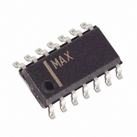
MAX13041ASD+T Maxim Integrated Products, MAX13041ASD+T Datasheet - Page 13

MAX13041ASD+T
Manufacturer Part Number
MAX13041ASD+T
Description
IC CAN TXRX +/-80V HS 14-SOIC
Manufacturer
Maxim Integrated Products
Type
Transceiverr
Datasheet
1.MAX13041ASD.pdf
(20 pages)
Specifications of MAX13041ASD+T
Number Of Drivers/receivers
1/1
Protocol
CAN
Voltage - Supply
4.75 V ~ 5.25 V
Mounting Type
Surface Mount
Package / Case
14-SOIC (3.9mm Width), 14-SOL
Lead Free Status / RoHS Status
Lead free / RoHS Compliant
activity. To reduce power consumption, common-mode
stabilization is disabled. SPLIT becomes high imped-
ance, and CANH and CANL are biased to ground by
the termination resistors. INH goes high impedance,
disabling one or more external voltage regulators (see
Table 1.)
The MAX13041 uses a set of seven internal flags for
system diagnosis and to indicate faults. Five of the
flags are available at different times to the CAN proto-
col controller on ERR. A logic-low on ERR indicates a
set flag or a fault (see Table 3.) Allow ERR to stabilize
for at least 8µs after changing operating modes.
UV
V
V
When UV
sleep mode to reduce power consumption. The device
±80V Fault-Protected High-Speed CAN Transceiver
Figure 4. State Diagram
CC(SLEEP)
I/O
with Low-Power Management and Wake-On CAN
NOM
drops below V
is set when supply voltage on V
NOM
for longer than t
is set, the MAX13041 enters low-power
______________________________________________________________________________________
I/O(SLEEP)
AND UV
STB = H AND EN = L
Supply Undervoltage: UV
NOM
CLEARED
UV(Vcc),
NOTES: H AND L ARE
FLAG SET =
FLAGS CLEARED
PWON/LISTEN-ONLY MODE
AND EN = L
STB = H
for longer than t
STANDBY MODE
(EN = L OR
FLAG SET)
STB = L
AND
or when voltage on
Flag Signaling
STB = L AND
CC
FLAG SET
drops below
AND EN = L
STB = H
UV(VI/O)
LOGIC STATE OF EN OR STB
SETTING PWON AND/OR WAKE-UP FLAG.
PWON AND WAKE-UP FLAG BOTH CLEARED.
AND EN = L
NOM
STB = L
AND FLAGS CLEARED
STB = L AND EN = H
STB = H AND EN = H
STB = H AND EN = L
(EN = L OR FLAG SET)
SLEEP MODE
.
STB = L AND
AND EN = H
remains in sleep mode for a minimum waiting time
before allowing the UV
waiting time is determined by the same timer used for
setting UV
by a local wake-up request triggered by a level change
on WAKE or by a wake-on-CAN event. UV
cleared by setting the PWON flag.
UV
V
standby mode to reduce power consumption. UV
cleared when the voltage on V
exceeds V
MAX13041 returns to the operating mode determined
by EN and STB.
PWON indicates the MAX13041 is in a power-on state.
PWON is set when V
and has subsequently recovered. This condition occurs
STB = H
BAT(STB)
AND FLAGS CLEARED
STB = L AND EN = H
BAT
is set when the voltage on V
FLAGS CLEARED
AND t > t
GO-TO-SLEEP COMMAND MODE
. When UV
NOM
BAT(STB)
H(MIN)
NORMAL MODE
AND EN = H
(t
STB = H
UV(VCC)
AND EN = H
BAT
BAT
STB = L
. Upon clearing UV
AND UV
STB = H AND EN = H
NOM
or t
has dropped below V
is set, the MAX13041 enters
V
NOM
BAT
UV(VIO)
flag to be cleared. This
CLEARED
Power-On Flag: PWON
Undervoltage: UV
BAT
.) UV
BAT
is restored and
NOM
drops below
NOM
is cleared
BAT
BAT(STB)
is also
BAT
, the
BAT
13
is


