LZC-70UA00-U7 LedEngin, LZC-70UA00-U7 Datasheet
LZC-70UA00-U7
Specifications of LZC-70UA00-U7


Related parts for LZC-70UA00-U7


LZC-70UA00-U7 Summary of contents
Page 1
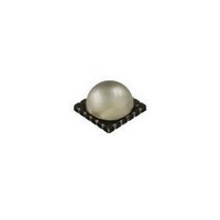
... Forensics Description The LZC-series emitter is rated for 40W power handling in an ultra compact package. With a small 9.0mm x 9.0mm x 5.4mm footprint, this package provides exceptional radiant flux density. The patented design has unparalleled thermal and optical performance. The high quality materials used in the package are chosen to optimize Radiant Flux and minimize stresses which results in monumental reliability and radiant flux maintenance ...
Page 2
... Typical Relative Dominant Wavelength Shift over Temperature . . . . . . . . . . . . . . . . . . 8 Typical Relative Radiant Flux . . . . . . . . . . . . . . . . . . . . . . . . . . . . . . . . . . . . . . . . . . . . 9 Typical Relative Radiant Flux over Temperature . . . . . . . . . . . . . . . . . . . . . . . . . . . . . . 9 Typical Forward Current Characteristics . . . . . . . . . . . . . . . . . . . . . . . . . . . . . . . . . . . . 10 Current Derating Curves . . . . . . . . . . . . . . . . . . . . . . . . . . . . . . . . . . . . . . . . . . . . . . . . 10 Emitter Tape & Reel Specifications . . . . . . . . . . . . . . . . . . . . . . . . . . . . . . . . . . . . . . . . 11 MCPCB Options Company Information . . . . . . . . . . . . . . . . . . . . . . . . . . . . . . . . . . . . . . . . . . . . . . . . . . 14 LedEngin, Inc. Table of Contents 2 LZC-00UA00 (R.1.3 – 110218) ...
Page 3
... LedEngin, Inc. Product Nomenclature Soak Requirements Standard Time (hrs) Conditions 168 85°C/ +5/-0 85 Accelerated Time (hrs) Conditions n/a n/a LZC-00UA00 (R.1.3 – 110218) ...
Page 4
... Forward Voltage Bins Table 4: Minimum Forward Voltage ( [1, 700mA F (V) 41.28 4 Maximum Radiant Flux (Φ) [1, 700mA F (mW) 6000 7500 9500 Maximum Peak Wavelength (λ [ 700mA F (nm) 395 400 405 410 Maximum Forward Voltage ( [1, 700mA F (V) 47.04 LZC-00UA00 (R.1.3 – 110218) ...
Page 5
... LEDs are not designed to be reverse biased. 4. Solder conditions per JEDEC 020D. See Reflow Soldering Profile Figure 3. 5. LedEngin recommends taking reasonable precautions towards possible ESD damages and handling the LZC-00UA00 in an electrostatic protected area (EPA). An EPA may be adequately protected by ESD controls as outlined in ANSI/ESD S6.1. Optical Characteristics @ T ...
Page 6
... Unless otherwise noted, the tolerance = ± 0.20 mm. 2. Recommended stencil thickness is 125µm. LedEngin, Inc. Tc Figure 1: Package outline drawing. 6 Pin Out Pad Series Function 2 1 Cathode 3 1 Cathode 5 2 Cathode 6 2 Cathode 14 2 Anode 15 2 Anode 17 1 Anode 18 1 Anode LZC-00UA00 (R.1.3 – 110218 ...
Page 7
... Figure 3: Reflow soldering profile for lead free soldering. 100 -90 -80 -70 -60 -50 -40 -30 -20 - Figure 4: Typical representative spatial radiation pattern. LedEngin, Inc. Reflow Soldering Profile Typical Radiation Pattern Angular Displacement (Degrees) 7 LZC-00UA00 (R.1.3 – 110218) ...
Page 8
... Figure 5: Relative spectral power vs. wavelength @ T Typical Relative Dominant Wavelength Shift over Temperature 5.0 4.0 3.0 2.0 1.0 0 Figure 6: Typical dominant wavelength shift vs. case temperature. LedEngin, Inc. 350 400 Wavelength (nm Case Temperature (ºC) 8 450 500 = 25°C. C 100 120 LZC-00UA00 (R.1.3 – 110218) ...
Page 9
... Figure 7: Typical relative Radiant Flux vs. forward current @ T Typical Relative Radiant Flux over Temperature 1.2 1 0.8 0.6 0.4 0 Figure 8: Typical relative Radiant Flux vs. case temperature. LedEngin, Inc. 400 600 I - Forward Current (mA Case Temperature (ºC) 9 800 1000 = 25°C. 100 120 LZC-00UA00 (R.1.3 – 110218) ...
Page 10
... Figure 10: Maximum forward current vs. ambient temperature based on T Notes for Figure 10: 1. Maximum current assumes that all four LED dice are operating concurrently at the same current. RΘ 2. [Junction to Case Thermal Resistance] for the LZC-series is typically 0.7°C/W. J-C RΘ [Junction to Ambient Thermal Resistance] = RΘ 3. J-A LedEngin, Inc ...
Page 11
... – – (see page 3 for base part number information designate the Flux bin (see table 2 ) ii. J & designate the Wavelength bin (see table 3) iii designate the Vf bin (see table 4) LedEngin, Inc. TBD TBD Figure 13: Emitter reel specifications (mm). 11 LZC-00UA00 (R.1.3 – 110218) ...
Page 12
... MCPCB contains Zener Diodes for enhanced ESD protection The LZC-7xxx00 Serial MCPCB option provides a convenient method to mount LedEngin’s single color LZC emitters. The six recessed features allow the use screws to attach the MCPCB to a heat sink. The MCPCB also contains Zener diodes for enhanced ESD protection ...
Page 13
... MCPCB contains Zener Diodes for enhanced ESD protection The LZC-Cxxx00 Parallel MCPCB option provides a convenient method to mount LedEngin’s single color LZC emitters. The six recessed features allow the use screws to attach the MCPCB to a heat sink. The MCPCB also contains Zener diodes for enhanced ESD protection ...
Page 14
... LedEngin is committed to providing products that conserve natural resources and reduce greenhouse emissions. LedEngin reserves the right to make changes to improve performance without notice. Please contact Sales@ledengin.com LedEngin, Inc. Company Information or (408) 492-0620 for more information. 14 LZC-00UA00 (R.1.3 – 110218) ...