1N5062GP-E3/1 Vishay, 1N5062GP-E3/1 Datasheet
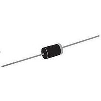
Rectifiers 1.0 Amp 800 Volt

1N5062GP-E3/1

Manufacturer Part Number
1N5062GP-E3/1
Description
Rectifiers 1.0 Amp 800 Volt
Manufacturer
Vishay
Datasheet

Specifications of 1N5062GP-E3/1

Product
Standard Recovery Rectifier
Configuration
Single
Reverse Voltage
800 V
Forward Voltage Drop
1.2 V
Recovery Time
2000 ns
Forward Continuous Current
1 A
Max Surge Current
50 A
Reverse Current Ir
5 uA
Mounting Style
Through Hole
Package / Case
DO-15
Maximum Operating Temperature
+ 175 C
Minimum Operating Temperature
- 65 C
Lead Free Status / Rohs Status
 Details
Standard Avalanche Sinterglass Diode
Features
Applications
Rectification diode, general purpose
Parts Table
Absolute Maximum Ratings
T
Document Number 86000
Rev. 1.5, 13-Apr-05
• Controlled avalanche characteristics
• Glass passivated
• Low reverse current
• High surge current loading
• Hermetically sealed axial-leaded glass envelope
• Lead (Pb)-free component
• Component in accordance to RoHS 2002/95/EC
1N5059
1N5060
1N5061
1N5062
Reverse voltage = Repetitive
peak reverse voltage
Peak forward surge current
Average forward current
Junction and storage
temperature range
Max. pulse energy in avalanche
mode, non repetitive (inductive
load switch off)
amb
and WEEE 2002/96/EC
= 25 °C, unless otherwise specified
Parameter
Part
see electrical characteristics
t
R
R
I
p
(BR)R
thJA
thJA
= 10 ms, half-sinewave
= 45 K/W, T
= 100K/W, T
= 1 A, indicutive load
Test condition
V
V
V
V
R
R
R
R
= 200 V; I
= 400 V; I
= 600 V; I
= 800 V; I
amb
amb
= 50 °C
= 75 °C
Type differentiation
FAV
FAV
FAV
FAV
e2
= 2 A
= 2 A
= 2 A
= 2 A
Mechanical Data
Case: SOD-57 Sintered glass case
Terminals: Plated axial leads, solderable per
MIL-STD-750, Method 2026
Polarity: Color band denotes cathode end
Mounting Position: Any
Weight: approx. 369 mg
1N5059
1N5060
1N5061
1N5062
Part
V
V
V
V
1N5059 to 1N5062
T
R
R
R
R
Symbol
j
= V
= V
= V
= V
I
I
I
= T
FSM
SOD-57
SOD-57
SOD-57
SOD-57
E
FAV
FAV
R
RRM
RRM
RRM
RRM
stg
Vishay Semiconductors
- 55 to + 175
Value
200
400
600
800
0.8
50
20
Package
2
www.vishay.com
Unit
mJ
°C
V
V
V
V
A
A
A
1

Related parts for 1N5062GP-E3/1

1N5062GP-E3/1 Summary of contents

Page 1

... FAV V = 600 FAV V = 800 FAV Test condition Part 1N5059 1N5060 1N5061 1N5062 = 50 °C amb = 75 °C amb = 1 A, indicutive load 1N5059 to 1N5062 Vishay Semiconductors Package SOD-57 SOD-57 SOD-57 SOD-57 Symbol Value Unit 200 V R RRM 400 V R RRM 600 V R RRM ...

Page 2

... Vishay Semiconductors Maximum Thermal Resistance °C, unless otherwise specified amb Parameter Junction ambient Lead length mm constant board with spacing 25 mm Electrical Characteristics °C, unless otherwise specified amb Parameter Forward voltage 2 Reverse current 100 µA Reverse breakdown voltage I R Reverse recovery time ...

Page 3

... SOD-57 26(1.014) min. Document Number 86000 Rev. 1.5, 13-Apr-05 1N5059 to 1N5062 0.1 V 15766 Figure 5. Typ. Diode Capacitance vs. Reverse Voltage 3.6 (0.140)max. ISO Method E 26(1.014) min. 4.0 (0.156) max. Vishay Semiconductors f =1 MHz 1 10 100 - Reverse Voltage ( 9538 0.82 (0.032) max. www.vishay.com 3 ...

Page 4

... Various national and international initiatives are pressing for an earlier ban on these substances. Vishay Semiconductor GmbH has been able to use its policy of continuous improvements to eliminate the use of ODSs listed in the following documents. 1. Annex A, B and list of transitional substances of the Montreal Protocol and the London Amendments respectively 2 ...

Page 5

... Vishay disclaims any and all liability arising out of the use or application of any product described herein or of any information provided herein to the maximum extent permitted by law. The product specifications do not expand or otherwise modify Vishay’ ...

Related keywords