GRM32ER61H106KA12L Murata, GRM32ER61H106KA12L Datasheet - Page 58
GRM32ER61H106KA12L
Manufacturer Part Number
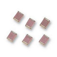
GRM32ER61H106KA12L
Description
CAPACITOR, 1210, 10UF, 50V
Manufacturer
Murata
Datasheet
1.GNM1M2R61A105ME14D.pdf
(221 pages)
Specifications of GRM32ER61H106KA12L
Dielectric Characteristic
X5R
Capacitance
10µF
Capacitance Tolerance
± 10%
Voltage Rating
50V
Capacitor Case Style
1210
Capacitor Mounting
SMD
Operating Temperature Range
-55°C To +85°C
Svhc
No SVHC
Rohs Compliant
Yes
Available stocks
Company
Part Number
Manufacturer
Quantity
Price
Company:

Part Number:
GRM32ER61H106KA12L
Manufacturer:
MURATA
Quantity:
400 000


!Note
• This PDF catalog is downloaded from the website of Murata Manufacturing co., ltd. Therefore, it’s specifications are subject to change or our products in it may be discontinued without advance notice. Please check with our
• This PDF catalog has only typical specifications because there is no space for detailed specifications. Therefore, please approve our product specifications or transact the approval sheet for product specifications before ordering.
sales representatives or product engineers before ordering.
!Note
Table A-1
(1)
(2)
56
No.
18
*1: Nominal values denote the temperature coefficient within a range of 25 C to 125 C (for C)/85 C (for other TC).
*2: Nominal values denote the temperature coefficient within a range of 20 C to 125 C (for C)/85 C (for other TC).
GRM Series Specifications and Test Methods (1) (Note 1)-Typical Inspection
Continued from the preceding page.
High
Temperature
Load
Char.
Char.
• Please read rating and !CAUTION (for storage, operating, rating, soldering, mounting and handling) in this catalog to prevent smoking and/or burning, etc.
• This catalog has only typical specifications because there is no space for detailed specifications. Therefore, please approve our product specifications or transact the approval sheet for product specifications before ordering.
5C
6C
6P
6R
6S
7U
1X
2C
3C
4C
2P
3P
4P
2R
3R
4R
2S
3S
4S
3U
4U
6T
2T
3T
4T
GRM Series Specifications and Test Methods (1) (Note 1)-Typical Inspection
Item
Appearance
Capacitance
Change
Q/D.F.
I.R.
Nominal Values (ppm/ C)*1
Nominal Values (ppm/ C)*2
The measured and observed characteristics should satisfy the
specifications in the following table.
No defects or abnormalities
Within 3% or 0.3pF
(whichever is larger)
30pF and over: QU350
10pF and over
30pF and below:
10pF and below:
C: Nominal Capacitance (pF)
More than 1,000M or 50 · F (whichever is smaller)
+350 to –1000
–150
–220
–330
–470
–750
–150
–150
–150
–220
–220
–220
–330
–330
–330
–470
–470
–470
–750
–750
Compensating Type
QU275+2.5C
QU200+10C
0
0
0
0
0
Temperature
30
60
60
60
60
60
120
60
120
250
60
120
250
60
120
250
60
120
250
60
120
250
120
250
When no "*" is added in PNs table, please refer to GRM Series Specifications and Test Methods (1).
Specifications
When "*" is added in PNs table, please refer to GRM Series Specifications and Test Methods (2).
Max.
Max.
0.58
0.87
2.33
3.02
4.09
5.46
8.78
0.82
1.37
2.56
B1, B3, R1, R6, R7, C8:
F1, F5, E4: Within 30%
[Except 10V max. and.
F1, F5: Within +30/–40%
[10V max. and CU1.0 F]
[B1, B3, R6, R7, C8]
W.V.: 100V
W.V.: 50/35/25/16/10V
W.V.: 6.3/4V
[E4]
W.V.: 25Vmin: 0.05 max.
[F1, F5]
W.V.: 25V min.
W.V.: 16/10V: 0.15 max.
W.V.: 6.3V: 0.2 max.
Please refer to individual specifications (our product specifications or the approval sheet).
–
–
–
–
–
–
–
–
–
–
–
–
–
–
–
High Dielectric Type
: 0.05 max. (CF0.068 F)
: 0.075 max. (CU0.068 F)
: 0.05 max.
: 0.075 max. (CF3.3 F)
: 0.125 max. (CU3.3 F)
: 0.075 max.(CF0.1 F)
: 0.125 max.(CU0.1 F)
–55
–55
CU1.0 F]
Within 12.5%
–0.24
–0.48
(Note 1) These Specifications and Test Methods indicate typical inspection.
–0.45
–0.90
–1.88
Min.
Min.
0.72
1.28
2.16
3.28
5.04
–
–
–
–
–
–
–
–
–
–
–
–
–
–
–
Capacitance Change from 25 C (%)
Capacitance Change from 20 C (%)
Apply 200%* of the rated voltage at the maximum operating
temperature 3 C for 1000 12 hours.
Set for 24 2 hours at room temperature, then measure.
The charge/discharge current is less than 50mA.
•Initial measurement for high dielectric constant type.
Apply 200% of the rated voltage* at the maximum operating
temperature 3 C for one hour. Remove and set for 24 2
hours at room temperature.
Perform initial measurement.
*GRM155C81E 683/104, GRM188C81E105,
GRM188C81E105, GRM21BR71H105, GRM21BR72A474,
GRM21BR71C225, GRM31CR71H475,
GRM32E R6/R7 YA106, GRM32D R7/R6/C8 1E106
Max.
Max.
0.40
0.59
1.61
2.08
2.81
3.75
6.04
0.49
0.82
1.54
1.32
1.65
2.36
1.70
2.03
2.74
2.30
2.63
3.35
3.07
3.40
4.12
4.94
5.65
–
–30
–25
–0.17
–0.33
–0.27
–0.54
–1.13
–0.45
–0.14
Min.
Min.
0.50
0.88
1.49
2.26
3.47
0.41
0.14
0.72
0.45
1.22
0.95
0.36
1.85
1.58
0.99
2.84
2.25
–
Test Method
: 150% of the rated voltage.
Max.
Max.
0.25
0.38
1.02
1.32
1.79
2.39
3.84
0.33
0.55
1.02
0.88
1.10
1.57
1.13
1.35
1.83
1.54
1.76
2.23
2.05
2.27
2.74
3.29
3.77
–
–10
–10
–0.11
–0.21
–0.18
–0.36
–0.75
–0.30
–0.09
Min.
Min.
0.32
0.56
0.95
1.44
2.21
0.27
0.09
0.48
0.30
0.81
0.63
0.24
1.23
1.05
0.66
1.89
1.50
–
C02E.pdf
10.12.20
Related parts for GRM32ER61H106KA12L
Image
Part Number
Description
Manufacturer
Datasheet
Request
R

Part Number:
Description:
Murata Microblower 20x20 DCDC Driver Board - Samples Only
Manufacturer:
Murata
Part Number:
Description:
357-036-542-201 CARDEDGE 36POS DL .156 BLK LOPRO
Manufacturer:
Murata
Datasheet:
Part Number:
Description:
Manufacturer:
Murata
Datasheet:
Part Number:
Description:
Manufacturer:
Murata
Datasheet:
Part Number:
Description:
Manufacturer:
Murata
Datasheet:
Part Number:
Description:
Manufacturer:
Murata
Datasheet:
Part Number:
Description:
Manufacturer:
Murata
Datasheet:
Part Number:
Description:
Manufacturer:
Murata
Datasheet:
Part Number:
Description:
Manufacturer:
Murata
Datasheet:
Part Number:
Description:
BLM21BD751SN1On-Board Type (DC) EMI Suppression Filters
Manufacturer:
Murata
Datasheet:
Part Number:
Description:
BLM15AG100SN1On-Board Type (DC) EMI Suppression Filters
Manufacturer:
Murata
Datasheet:
Part Number:
Description:
NFE31PT222Z1E9On-Board Type (DC) EMI Suppression Filters
Manufacturer:
Murata
Datasheet:
Part Number:
Description:
Chip Coil
Manufacturer:
Murata
Datasheet:
Part Number:
Description:
Chip Coil
Manufacturer:
Murata
Datasheet: