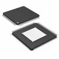
DS26303LN-75+ Maxim Integrated Products, DS26303LN-75+ Datasheet - Page 22

DS26303LN-75+
Manufacturer Part Number
DS26303LN-75+
Description
IC LIU E1/T1/J1 3.3V 144-ELQFP
Manufacturer
Maxim Integrated Products
Type
Line Interface Units (LIUs)r
Datasheet
1.DS26303L-120.pdf
(101 pages)
Specifications of DS26303LN-75+
Number Of Drivers/receivers
8/8
Protocol
T1/E1/J1
Voltage - Supply
3.135 V ~ 3.465 V
Mounting Type
Surface Mount
Package / Case
144-LQFP Exposed Pad, 144-eLQFP, 144-HLQFP
Lead Free Status / RoHS Status
Lead free / RoHS Compliant
Figure 4-4. Serial Port Operation for Read Access with CLKE = 1
4.1.3 Parallel Port Operation
When using the parallel interface on the DS26303 the user has the option for either multiplexed bus operation or
non-multiplexed bus operation. The ALE pin is pulled high in non-multiplexed bus operation. The DS26303 can
operate with either Intel or Motorola bus-timing configurations selected by MOTEL pin. This pin being high selects
the Intel mode. The parallel port is only operational if the MODESEL pin is pulled high. The following table lists all
the pins and their functions in the parallel port mode. See the timing diagrams in Section
Table 4-3. Parallel Port Mode Selection and Pin Functions
4.1.4
INTB must be pulled high externally with a 10kΩ resistor for wired-OR operation. If a wired-OR operation is not
required, the INTB pin can be configured to be high when not active by setting register GISC.INTM.
There are three events that can potentially trigger an interrupt: a loss of signal (LOS), driver fault monitor (DFM), or
an alarm indication signal (AIS). The interrupt functions as follows:
•
•
•
Note: The BERT can also generate an interrupt. The BERT interrupt handling is described in Section 6.9.2.
MODESEL, MOTEL,
When a status bit (AIS:AISn, DFMS:DFMSn, or LOSS:LOSn) changes on an interruptible event, the
corresponding interrupt status bit (AISIS:AISIn, DFMIS:DFMISn, or LOSIS:LOSISn) is set. The INTB pin will go
low if the event is enabled through the corresponding interrupt-enable bit (AISIE:AISIEn, DFMIE:DFMIEn, or
LOSIE:LOSIEn).
When an interrupt occurs, the host processor must read the three interrupt status registers (AISIS, DFMIS, and
LOSIS) to determine the source of the interrupt. If the interrupt status registers are set for clear-on-read
(GISC.CWE reset), the read also clears the interrupt status register, which clears the output INTB pin. If the
interrupt status registers are set for clear-on-write (GISC.CWE set), a 1 must be written to the interrupt status
bit (AISIS:AISIn, DFMIS:DFMISn, or LOSIS:LOSISn) in order to clear it, which clears the output INTB pin.
Subsequently, the host processor can read the corresponding status register (AIS, DFMS, or LOSS) to check
the real-time status of the event.
Interrupt Handling
SDI
SDO
CSB
MUX
100
110
101
111
SCLK
0
(lsb)
1
A1
2
A2
Non-multiplexed Motorola
3
Non-multiplexed Intel
Multiplexed Motorola
PARALLEL HOST
A3
Multiplexed Intel
4
INTERFACE
A4
5
A5
6
A6
7
DS26303: 3.3V, T1/E1/J1, Short-Haul, Octal Line Interface Unit
22 of 101
(msb)
X
8
CSB, ACKB, DSB, RWB, ASB, A[4:0], D[7:0], INTB
CSB, RDY, WRB, RDB, ALE, A[4:0], D[7:0], INTB
CSB, ACKB, DSB, RWB, ASB, AD[7:0], INTB
CSB, RDY, WRB, RDB, ALE, AD[7:0], INTB
D0
(lsb)
9
D1
10
ADDRESS, DATA, AND CONTROL
D2
11
D3
12
D4
13
D5
10
14
for more details.
D6
15
(msb)
D7
16


