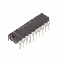
MAX3235ECPP+G36 Maxim Integrated Products, MAX3235ECPP+G36 Datasheet - Page 6

MAX3235ECPP+G36
Manufacturer Part Number
MAX3235ECPP+G36
Description
IC TXRX RS-232 DL 20-DIP
Manufacturer
Maxim Integrated Products
Type
Transceiverr
Datasheet
1.MAX3235ECWP.pdf
(12 pages)
Specifications of MAX3235ECPP+G36
Number Of Drivers/receivers
2/2
Protocol
RS232
Voltage - Supply
4.5 V ~ 5.5 V
Mounting Type
Through Hole
Package / Case
20-DIP (0.300", 7.62mm)
Lead Free Status / RoHS Status
Lead free / RoHS Compliant
±15kV ESD-Protected, 1µA, 250kbps, 3.3V/5V, Dual
RS-232 Transceivers with Internal Capacitors
The MAX3233E/MAX3235E’s internal power supply
consists of a regulated dual charge pump that provides
output voltages of +5.5V (doubling charge pump) and
-5.5V (inverting charge pump), with no external capaci-
tors. The charge pump operates in discontinuous
mode: if the output voltages are less than 5.5V, the
charge pump is enabled; if the output voltages exceed
5.5V, the charge pump is disabled.
The transmitters are inverting level translators that
convert CMOS-logic levels to 5.0V EIA/TIA-232 levels.
The devices guarantee a 250kbps data rate with worst-
case loads of 3kΩ in parallel with 1000pF, providing
compatibility with PC-to-PC communication software
(such as LapLink™). Transmitters can be paralleled to
drive multiple receivers. Figure 1 shows a complete
system connection.
When FORCEOFF is driven to ground or when the Auto-
Shutdown Plus circuitry senses that all receiver and
transmitter inputs are inactive for more than 30sec, the
transmitters are disabled and the outputs go into a high-
impedance state. When powered off or shut down, the
outputs can be driven to ±12V. The transmitter inputs
do not have pull-up resistors. Connect unused inputs to
GND or V
The receivers convert RS-232 signals to CMOS-logic
output levels. They feature inverting outputs that always
remain active (Table 1).
The MAX3233E/MAX3235E feature an INVALID output
that is enabled low when no valid RS-232 voltage levels
have been detected on all receiver inputs. Because
INVALID indicates the receiver input’s condition, it is
independent of FORCEON and FORCEOFF states
(Figures 2 and 3).
The devices achieve a 1µA supply current with Maxim’s
AutoShutdown Plus feature, which operates when
FORCEOFF is high and a FORCEON is low. When these
devices do not sense a valid signal transition on any
receiver or transmitter input for 30sec, the on-board
charge pumps are shut down, reducing supply current
to 1µA. This occurs if the RS-232 cable is disconnected,
or if the connected peripheral transmitters are turned off
and the UART driving the transmitter inputs is inactive.
The system turns on again when a valid transition is
LapLink is a trademark of Traveling Software.
6
_______________Detailed Description
_______________________________________________________________________________________
Dual Charge-Pump Voltage Converter
CC
.
AutoShutdown Plus Mode
RS-232 Transmitters
RS-232 Receivers
Figure 2b. INVALID Functional Diagram, INVALID High
Figure 1. Interface Under Control of PMU
Figure 2a. INVALID Functional Diagram, INVALID Low
+0.3V
-0.3V
+2.7V
-2.7V
R_IN
R_IN
INVALID DEASSERTED IF ANY RECEIVER INPUT HAS BEEN ABOVE +2.7V OR BELOW
-2.7V FOR 1µs.
MANAGEMENT
CONTROLLER
INVALID ASSERTED IF ALL RECEIVER INPUTS ARE BETWEEN +0.3V AND -0.3V FOR
AT LEAST 80µs.
CPU
KEYBOARD
POWER-
UNIT OR
INVALID
FORCEOFF
FORCEON
WITH
UART
CHIP
I/O
MAX3233E
MAX3235E
TIMER
TIMER
80µs
80µs
R
R
INVALID
INVALID
RS-232


