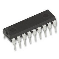
HT12E HOLTEK, HT12E Datasheet

HT12E
Specifications of HT12E
Available stocks
Related parts for HT12E
HT12E Summary of contents
Page 1
... Other remote control systems bits via infrared transmission medium upon receipt of a trigger signal. The capability to select a TE trigger on the HT12E or a DATA trigger on the HT12A further enhances the application flexibility of the 2 ries of encoders. The HT12A additionally provides a 38kHz carrier for infrared systems. ...
Page 2
... Block Diagram TE Trigger HT12E DATA Trigger HT12A The address data pins are available in various combinations (refer to the address/data table). Note: Pin Assignment Rev. 1.20 HT12A/HT12E 2 February 20, 2009 ...
Page 3
... VSS I VDD I Note: D8~D11 are all data input and transmission enable pins of the HT12A transmission enable pin of the HT12E. Approximate Internal Connections Rev. 1.20 Description Input pins for address A0~A7 setting These pins can be externally set to VSS or left open Input pins for address/data AD8~AD11 setting ...
Page 4
... Operating Current DD I Output Drive Current DOUT V H Input Voltage Input Voltage IL f Oscillator Frequency OSC R TE Pull-high Resistance TE Rev. 1.20 +5.5V Supply Voltage (HT12E) ........................... 0.3V to 13V SS +0.3V Storage Temperature ............................ 125 C DD Test Conditions Min. V Conditions DD 2.4 3V Oscillator stops load f =455kHz OSC ...
Page 5
... The 2 series of encoders begin a 4-word transmission cycle upon receipt of a transmission enable (TE for the HT12E or D8~D11 for the HT12A, active low). This cycle will repeat itself as long as the transmission enable (TE or D8~D11) is held low. Once the transmission enable returns high the encoder output completes its final cycle and then stops as shown below ...
Page 6
... A0 to AD11 for the HT12E encoder and A0 to D11 for the HT12A encoder. During information transmission these bits are transmitted with a preceding synchronization bit. If the trigger signal is not applied, the chip enters the standby mode and consumes a reduced current of less than 1 A for a supply voltage of 5V ...
Page 7
... A1 A2 Transmission Enable For the HT12E encoders, transmission is enabled by applying a low signal to the TE pin. For the HT12A encoders, transmission is enabled by applying a low signal to one of the data pins D8~D11. Two Erroneous HT12E Application Circuits The HT12E must follow closely the application circuits provided by Holtek (see the Application circuits ). ...
Page 8
... Flowchart HT12A Note: D8~D11 are transmission enables of the HT12A the transmission enable of the HT12E. Rev. 1.20 HT12A/HT12E HT12E 8 February 20, 2009 ...
Page 9
... Oscillator Frequency vs. Supply Voltage The recommended oscillator frequency is f Application Circuits Rev. 1.20 (decoder (HT12E encoder) OSCD OSCE 1 f (HT12A encoder) OSCE 3 9 HT12A/HT12E February 20, 2009 ...
Page 10
... Dimensions in mil Min. Nom. 880 240 115 115 14 45 100 300 Dimensions in mil Min. Nom. 845 240 115 115 14 45 100 300 10 HT12A/HT12E Max. 920 280 195 150 22 70 325 430 Max. 880 280 195 150 22 70 325 430 February 20, 2009 ...
Page 11
... MO-095a (see fig2) Symbol Rev. 1.20 Dimensions in mil Min. Nom. 845 275 120 110 14 45 100 300 11 HT12A/HT12E Max. 885 295 150 150 22 60 325 430 February 20, 2009 ...
Page 12
... SOP (300mil) Outline Dimensions MS-013 Symbol Rev. 1.20 Dimensions in mil Min. Nom. 393 256 12 496 HT12A/HT12E Max. 419 300 20 512 104 February 20, 2009 ...
Page 13
... SOP 20W Symbol Description A Reel Outer Diameter B Reel Inner Diameter C Spindle Hole Diameter D Key Slit Width T1 Space Between Flange T2 Reel Thickness Rev. 1.20 HT12A/HT12E Dimensions in mm 330.0 1.0 100.0 1.5 +0.5/-0.2 13.0 2.0 0.5 +0.3/-0.2 24.8 30.2 0.2 13 February 20, 2009 ...
Page 14
... P1 Cavity to Perforation (Length Direction) A0 Cavity Length B0 Cavity Width K0 Cavity Depth t Carrier Tape Thickness C Cover Tape Width Rev. 1.20 HT12A/HT12E Dimensions in mm +0.3/-0.1 24.0 12.0 0.1 1.75 0.10 11.5 0.1 +0.1/-0.0 1.5 +0.25/-0.00 1.50 4.0 0.1 2.0 0.1 10.8 0.1 13 ...
Page 15
... Holtek s products are not authorized for use as critical components in life support devices or systems. Holtek reserves the right to alter its products without prior notification. For the most up-to-date information, please visit our web site at http://www.holtek.com.tw. Rev. 1.20 HT12A/HT12E 15 February 20, 2009 ...


