ALC42A221DC450 Kemet, ALC42A221DC450 Datasheet
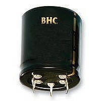
Aluminum Electrolytic Capacitors - Snap In 220uF 450VDC 20% 35 X 35mm

ALC42A221DC450

Manufacturer Part Number
ALC42A221DC450
Description
Aluminum Electrolytic Capacitors - Snap In 220uF 450VDC 20% 35 X 35mm
Manufacturer
Kemet
Datasheet

Specifications of ALC42A221DC450

Capacitance
220 uF
Tolerance
20 %
Voltage Rating
450 Volts
Operating Temperature Range
- 40 C to + 105 C
Diameter
36 mm
Length
67 mm
Product
Aluminum Electrolytic Capacitors
Termination Style
Snap In
Lead Free Status / Rohs Status
 Details
Designed for applications where high
reliability and compact sizes are important
such as switch mode power supplies and
frequency converters.
ALC42 Series
• compact size
• 2000 hours at 105 °c (ur, ir applied)
• Excellent surge voltage capability
• optimized designs available on request
standards
capacitance range
capacitance tolerance
rated voltage u
surge voltage u
surge voltage u
(short duration)
leakage current i
operational life time
+105°c, u
+105°c, u
shelf life
temperature range
r
r
, i
aPPlication
r
r
s
ss
l
IEC 60384-4 Long Life Grade 40/105/56,
120 – 6800 µF
–20 to +20%
200 - 450 VDC
1.15 x U
1.10 x U
= 0.003 x C
is the smaller. Note, C
2000 hrs at 0V +85°C, or 30000 hrs at 0V +40°C
–40 to +105°C (Operating) -55°C to +105°C (Storage)
200
250
350
400
415
450
500
Can Diameter
30, 35, 40, 45, 50 2000 hrs
Can Diameter
30, 35, 40, 45, 50 11000 hrs
U
R
350
400
500
520
530
550
600
U
R
R
(for U
(for U
SS
R
x U
R
R
The ALC42 (105°C) is a high CV snap-in
version of the ALC40 range.
< 250 VDC)
> 350 VDC)
R
(µA) or 6mA whichever
R
is in µF.
105°C
sPEcification
basic dEsign
Test Condition:
< 30s surge, 1000 cycles @ 105°C
Test Condition:
< 500ms surge, 100 cycles @ 20°C
Test Condition:
U
End of Life requirement:
ΔC/C
ESR
I
L
R
, 5mins., 20°C
< ±10%
< 2 x initial ESR value
< initial specified limit
RoHS
Compliant

Related parts for ALC42A221DC450

ALC42A221DC450 Summary of contents

Page 1

ALC42 Series • compact size • 2000 hours at 105 °c (ur, ir applied) • Excellent surge voltage capability • optimized designs available on request aPPlication Designed for applications where high reliability and compact sizes are important such as switch ...

Page 2

... STYLE C = 6.3 ± 1 STYLE E = 4.0 ± 2.0max STYLE J + 3.75 mounting These capacitors are designed to be mounted by their terminations alone, and may be used in any position. Dummy pins must be isolated on 4 and 5 pin styles. terminal style description 2 pin 2 pin Pin length 6.3±1 4.0±1 ...

Page 3

alc42 105°c cap case (µf) size (mm) 560 30x30 680 30x35 820 30x40 1000 35x35 1000 40x30 1200 30x50 1200 35x40 1200 40x35 1500 35x50 1500 40x40 1800 40x45 2200 35x60 2200 40x50 2200 40x55 2700 35x80 2700 40x60 3300 ...

Page 4

... ALC42A182EP400 6.96 12.32 ALC42G222FP400 7.48 12.17 ALC42G272KP400 1.13 2.69 ALC42A121CB450 1.40 3.20 ALC42A181CC450 1.69 3.73 ALC42A221CD450 1.80 3.66 ALC42A221DC450 2.06 4.67 ALC42A271CF450 2.08 4.19 ALC42A271DD450 1.78 2.90 ALC42A271EB450 2.13 3.54 ALC42A331EC450 2.44 4.12 ALC42A391ED450 2.78 4.94 ALC42A471DF450 2.70 4.59 ALC42A471EE450 3 ...

Page 5

... An estimation is also given at 40°C. The expected failure rate for this capacitor range is based on our periodic test results for capacitors with structural similarity. Failure rate is frequently quoted in FIT (Failures In Time) where 1 FIT = failures per -9 hour ...

Related keywords