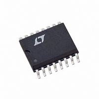
LTC1062CSW Linear Technology, LTC1062CSW Datasheet

LTC1062CSW
Specifications of LTC1062CSW
Available stocks
Related parts for LTC1062CSW
LTC1062CSW Summary of contents
Page 1
... The device can be operated with single or dual supplies ranging from ±2.5V to ±9V. The LTC1062 is manufactured using Linear Technology’s enhanced LTCMOS , LTC and LT are registered trademarks of Linear Technology Corporation. LTCMOS is a trademark of Linear Technology Corporation. DC ACCURATE OUTPUT – ...
Page 2
... Pin 4 (Pin 6 in SW16 CLK C = 0.01µ 25.78k + f = 100kHz, Pin 4 (Pin 6 in SW16 CLK C = 0.01µ 25.78k + f = 400kHz, Pin 0.01µ 6.5k CLK + f = 400kHz, Pin 0.01µ 6.5k CLK ORDER PART NUMBER LTC1062CSW 14 B OUT 13 OUT + OSC 90°C/W JA MIN TYP MAX 4 0.00 – ...
Page 3
ELECTRICAL CHARACTERISTICS ture range, otherwise specifications are at T Figure 1. PARAMETER Internal Buffer Bias Current Offset Voltage Voltage Swing Short-Circuit Current Source/Sink Clock (Note 3) Internal Oscillator Frequency Max Clock Frequency Pin 5 (Pin 11 in SW16) Source or ...
Page 4
LTC1062 W U TYPICAL PERFOR A CE CHARACTERISTICS Passband Gain vs Input Frequency and Temperature 0 ± 100kHz CLK 0 125° 1.62 2π –55°C A ...
Page 5
W BLOCK DIAGRA For Adjusting Oscillator Frequency, Insert a 50k Pot in Series with C SWITCHED FB 1 CAPACITOR NETWORK AGND 2 f CLK – CLOCK GEN 4 ÷ ÷ AC TEST CIRCUIT R = ...
Page 6
LTC1062 U U APPLICATIO S I FOR ATIO Filter Input Voltage Range Every node of the LTC1062 typically swings within 1V of either voltage supply, positive or negative. With the appro- priate external (RC) values, the amplitude response of all ...
Page 7
U U APPLICATIO S I FOR ATIO Divide (Pin connecting Pin mid supplies clock frequency driving the internal switched capacitor network is the oscillator frequency ...
Page 8
LTC1062 U TYPICAL APPLICATIO Adding an External (R1, C1) to Eliminate the Clock Feedthrough and Filtering AC Signals from High DC Voltages R 25. 0.01µ OUT HIGH DC ...
Page 9
U TYPICAL APPLICATIO S R1 10k Frequency Response of the Bandpass Filter ± R′1 = 0.8 –10 R′2 – 100mV IN –30 –40 ...
Page 10
LTC1062 U TYPICAL APPLICATIO S 25. 1µ AGND LTC1062 3 – – DIVIDER RATIO 10Hz, 10TH ORDER DC ACCURATE LOWPASS FILTER 60dB/OCTAVE ROLLOFF 0.5dB PASSBAND ERROR, 0dB DC GAIN MAXIMUM ATTENUATION 110dB (f ...
Page 11
U TYPICAL APPLICATIO S 7th Order 100Hz Lowpass Filter with Continuous Output Filtering, Output Buffering and Gain Adjustment 2. –5V 5V THE LTC1052 IS CONNECTED AS A 2ND ORDER SALLEN AND KEY LOWPASS FILTER WITH A CUTOFF FREQUENCY ...
Page 12
LTC1062 U TYPICAL APPLICATIO S R 9.09k 1µ AGND 3 – – DIVIDER RATIO 12 A Lowpass Filter with a 60Hz Notch R6 19.35k R3 R4 20k 10k R2 20k 8 ...
Page 13
PACKAGE DESCRIPTIO CORNER LEADS OPTION .045 – .068 (1.143 – 1.650) FULL LEAD OPTION .300 BSC (7.62 BSC) .008 – .018 (0.203 – 0.457) NOTE: LEAD DIMENSIONS APPLY TO SOLDER DIP/PLATE OR TIN PLATE LEADS U J8 Package 8-Lead CERDIP ...
Page 14
LTC1062 PACKAGE DESCRIPTIO .300 – .325 (7.620 – 8.255) .008 – .015 (0.203 – 0.381) +.035 .325 –.015 ( ) +0.889 8.255 –0.381 NOTE: 1. DIMENSIONS ARE MILLIMETERS *THESE DIMENSIONS DO NOT INCLUDE MOLD FLASH OR PROTRUSIONS. MOLD FLASH OR ...
Page 15
... MOLD FLASH OR PROTRUSIONS SHALL NOT EXCEED .006" (0.15mm) Information furnished by Linear Technology Corporation is believed to be accurate and reliable. However, no responsibility is assumed for its use. Linear Technology Corporation makes no represen- tation that the interconnection of its circuits as described herein will not infringe on existing patent rights. ...
Page 16
... Clock Tunable, fc ≤ 120kHz Very Low Noise, 256Hz ≤ fc ≤ 256kHz Continuous Time, Very High Dynamic Range, PGA Included No External Clock Required, fc ≤ 64kHz, S08 No External Clock Required, fc ≤ 300kHz, S08 www.linear.com 1062fd LW/TP 1102 1K REV D • PRINTED IN USA LINEAR TECHNOLOGY CORPORATION 1994 ...


