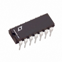
LTC1064-7CN Linear Technology, LTC1064-7CN Datasheet

LTC1064-7CN
Specifications of LTC1064-7CN
Related parts for LTC1064-7CN
LTC1064-7CN Summary of contents
Page 1
... Bessel), while at three times the cutoff frequency, the filter attains 68dB attenuation (vs 30dB for Bessel). The cutoff frequency of the LTC1064-7 is tuned via an external TTL or CMOS clock. The LTC1064-7 features wide dynamic range. With single 5V supply, the S/N + THD is 76dB. Optimum 92dB S/N is obtained with ± ...
Page 2
... Operating Temperature Range LTC1064-7C ....................................... – 40°C to 85°C LTC1064-7M OBSOLETE .............. – 55°C to 125°C ≤ Lead Temperature (Soldering, 10 sec)................. 300°C + 0.3V ORDER PART NUMBER GND 3 LTC1064-7CN + V 4 GND (A) 7 INV ( PACKAGE 16-LEAD PLASTIC SO (WIDE) LTC1064-7CJ = 110°C, θ T JMAX LTC1064-7MJ The ● ...
Page 3
... ±5V 50: ±5V 100: ±2.375V 25° ±5V 25° ±7.5V 25° LTC1064-7 = 10kHz or 20kHz 1MHz, TTL or CLK MIN TYP MAX ±1.0 ±1.0 ± 2.0 ● ± 2.0 ● 59.7 ± 0.5 117.0 ± 1.0 ● 58.6 59.7 60.7 ● 115.0 117.0 119.0 ± ...
Page 4
... F is arbitrarily called the “phase factor” expressed in degrees. The phase factor allows the calculation of the phase at a given frequency. Example: The phase shift at 14kHz of the LTC1064-7 shown in Figure 1 is: phase shift = 180° – 430° (14kHz/20kHz) ± nonlinearity = –121° ± – ...
Page 5
... GAIN – 60 –1 –120 –2 PHASE –180 –3 –240 –4 –300 –5 –6 –360 1064-7 G06 LTC1064-7 Phase Factor vs f CLK (Typical Unit) 485 V = ± 100:1 475 CLK C 70°C 465 455 445 25°C 435 0°C 425 415 3.0 3.5 0.5 1 ...
Page 6
... LTC1064 TYPICAL PERFOR A Passband Gain vs Frequency and f CLK ±7. 1MHz S CLK 25° 2MHz A CLK ( 50 3MHz CLK C 3 CLK 4MHz CLK 5MHz CLK 1 0 –1 D – – 3 –4 – 100 1000 FREQUENCY (kHz) 1064-7 G08 Passband Gain vs Frequency and f CLK SINGLE 0.5MHz ...
Page 7
... V S ≤ 2.5MHz f CLK ( 50:1 OR 100:1 CLK 0°C TO 70° 0.2 0.6 0 0.4 0.8 FREQUENCY (f /FREQUENCY) CUTOFF LTC1064-7 THD + Noise vs Frequency – SINGLE 5V S – 0.5V IN RMS f = 500kHz – 50 CLK ( 100:1 CLK C – 55 (PINS 2V) – 60 –65 –70 –75 –80 –85 – ...
Page 8
... LTC1064 TYPICAL PERFOR A Table 1. Passband Gain and Phase = ±7.5V 50: 25°C S CLK C A FREQUENCY (kHz) GAIN (dB 1MHz (Typical Unit) CLK 0.000 – 0.086 5.000 – 0.086 10.000 – 0.334 15.000 – 1.051 20.000 – 3.316 f = 2MHz (Typical Unit) CLK 0.000 – 0.131 10.000 – ...
Page 9
... Unit) CLK 180.00 0.000 70.81 5.000 – 38.39 10.000 – 146.85 15.000 – 256.10 20.000 LTC1064 50: 25°C CLK C A GAIN (dB) PHASE (DEG) – 0.134 180.00 – 0.134 73.52 – 0.391 – 33.67 – 1.109 – ...
Page 10
... Figure 2. Dual Supply Operation for LTC1064 0.1µ 10k 10k 1µF Figure 3. Single Supply Operation for an f Clock Input Pin (11) Any TTL or CMOS clock source with a square-wave output and 50% duty cycle (±10 adequate clock source for the device. The power supply for the clock source should not be the filter’ ...
Page 11
... RMS 300µV cannot be reduced with post filtering. For instance, the RMS 650µV LTC1064-7 wideband noise at ±5V supply is 105µV RMS 95µV of which have frequency contents from RMS the filter’s cutoff frequency. The total wideband noise (µ nearly independent of the value of the clock ...
Page 12
... CLK If, for instance, an LTC1064-7 operating with a 100kHz 3.0 clock and 1kHz cutoff frequency receives a 98kHz, 10mV 2.5 2.0 input signal, a 2kHz, 143µV 1 ...
Page 13
... RAD TYP 0° – 15° .045 – .065 (1.143 – 1.651) .014 – .026 (0.360 – 0.660) OBSOLETE PACKAGE LTC1064 .220 – .310 (5.588 – 7.874 .200 (5.080) MAX .015 – .060 (0.381 – 1.524) .100 .125 (2.54) (3.175) ...
Page 14
... LTC1064-7 PACKAGE DESCRIPTIO .300 – .325 (7.620 – 8.255) .008 – .015 (0.203 – 0.381) +.035 .325 –.015 ( ) +0.889 8.255 –0.381 NOTE: INCHES 1. DIMENSIONS ARE MILLIMETERS *THESE DIMENSIONS DO NOT INCLUDE MOLD FLASH OR PROTRUSIONS. MOLD FLASH OR PROTRUSIONS SHALL NOT EXCEED .010 INCH (0.254mm) ...
Page 15
... NOTE 3 N/2 1 .093 – .104 × 45° (2.362 – 2.642) 0° – 8° TYP .050 (1.270) BSC .014 – .019 (0.356 – 0.482) LTC1064-7 .398 – .413 (10.109 – 10.490) NOTE .394 – .419 (10.007 – 10.643) N/2 ...
Page 16
... OF AT LEAST 0.2 INCHES BETWEEN ANY OUTPUT OR INPUT PIN AND THE f LINE. CLK RELATED PARTS PART NUMBER DESCRIPTION LTC1064 Universal Filter Building Block LTC1064-1/2/3/4 8th Order Low Pass Filters, F LTC1164 Universal Filter Building Block LTC1164-5/6/7 8th Order Low Pass Filters, F LTC1264 Universal Filter Building Block LTC1264-7 8th Order Low Pass Filter, F LT6600-2 ...


