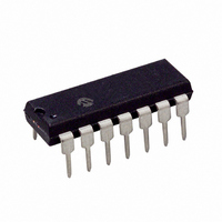
MCP25055-I/P Microchip Technology, MCP25055-I/P Datasheet - Page 47

MCP25055-I/P
Manufacturer Part Number
MCP25055-I/P
Description
IC I/O EXPANDER CAN 8B 14DIP
Manufacturer
Microchip Technology
Specifications of MCP25055-I/P
Mounting Type
Through Hole
Interface
1-Wire, CAN
Number Of I /o
8
Interrupt Output
No
Frequency - Clock
4MHz
Voltage - Supply
2.7 V ~ 5.5 V
Operating Temperature
-40°C ~ 85°C
Package / Case
14-DIP (0.300", 7.62mm)
Includes
ADC, Memory, PWM
Bus Frequency
4MHz
No. Of I/o's
8
Supply Voltage Range
2.7V To 5.5V
Digital Ic Case Style
DIP
No. Of Pins
14
Operating Temperature Range
-40°C To +85°C
Data Rate Max
1Mbps
Leaded Process Compatible
Yes
Rohs Compliant
Yes
Lead Free Status / RoHS Status
Lead free / RoHS Compliant
For Use With
DV250501 - KIT DEV CAN MCP250XX
Lead Free Status / RoHS Status
Lead free / RoHS Compliant, Lead free / RoHS Compliant
Other names
MCP25055I/P
Available stocks
Company
Part Number
Manufacturer
Quantity
Price
Company:
Part Number:
MCP25055-I/P
Manufacturer:
MICROCHIP
Quantity:
12 000
8.0
8.1
There are a number of special circuits in the
MCP2502X/5X that deal with the needs of real-time
applications. These features are intended to maximize
system reliability, minimize cost through elimination of
external components and provide power-saving
operating modes. These are:
• Oscillator selection
• Reset
• SLEEP
• In-Circuit Serial Programming
Several oscillator options are offered to allow the
device to fit the application. XT and HS modes allow
the device to support a wide range of crystal
frequencies while the LP crystal option saves power.
Two timers are implemented to offer necessary delays
on power-up. One is the Oscillator Start-up Timer
(OST), intended to keep the device in reset until the
crystal oscillator is stable. The other is the Power-up
Timer (PWRT), which provides a fixed delay of 72 ms
(nominal) on power-up only, designed to keep the part
in reset while the power supply stabilizes. With these
two timers on-chip, most applications need no external
reset circuitry.
SLEEP mode is designed to offer a very low current
power-down mode. The user can wake-up from SLEEP
through external reset, transmit-on-change or CAN bus
activity.
A set of configuration bits are used to select various
options.
FIGURE 8-1:
© 2007 Microchip Technology Inc.
- Power-on Reset (POR)
- Power-up Timer (PWRT)
- Oscillator Start-up Timer (OST)
C1
C2
SPECIAL FEATURES OF THE
MCP2502X/5X
Description
XTAL
OSC1
OSC2
CRYSTAL/CERAMIC
RESONATOR
OPERATION
R
F
SLEEP
TO INTERNAL
MCP2505X
LOGIC
FIGURE 8-2:
8.2
The configuration bits can be either programmed (read
as ‘0’) or unprogrammed (read as ‘1’) to select various
device configurations. These bits are mapped in
program memory location 2007h. The configuration
register is actually beyond program memory space and
belongs to the special test/configuration memory space
(2000h-3FFFh) that can be accessed only during
programming.
8.3
Four different oscillator modes may be selected. The
user
(F
these modes:
• LP = Low-Power Crystal
• XT = Crystal/Resonator
• HS = High-speed Crystal Resonator
In all modes, a crystal or ceramic resonator is
connected to the OSC1/CLKIN and OSC2/CLKOUT
pins to establish oscillation (Figure 8-1). The oscillator
design requires the use of a parallel-cut crystal. The
device can also have an external clock source to drive
the OSC1/CLKIN pin (Figure 8-2).
The device will default to HS mode if the CONFIG
register is not programmed.
ext. System
OSC
Clock from
1:F
can
Configuration Bits
Oscillator Configurations
OSC
0) in the CONFIG register to select one of
program
Open
MCP2502X/5X
EXTERNAL CLOCK INPUT
OPERATION
two
OSC1
OSC2
MCP2505X
configuration
DS21664D-page 47
bits


