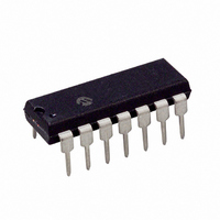
MCP25055-I/P Microchip Technology, MCP25055-I/P Datasheet - Page 6

MCP25055-I/P
Manufacturer Part Number
MCP25055-I/P
Description
IC I/O EXPANDER CAN 8B 14DIP
Manufacturer
Microchip Technology
Specifications of MCP25055-I/P
Mounting Type
Through Hole
Interface
1-Wire, CAN
Number Of I /o
8
Interrupt Output
No
Frequency - Clock
4MHz
Voltage - Supply
2.7 V ~ 5.5 V
Operating Temperature
-40°C ~ 85°C
Package / Case
14-DIP (0.300", 7.62mm)
Includes
ADC, Memory, PWM
Bus Frequency
4MHz
No. Of I/o's
8
Supply Voltage Range
2.7V To 5.5V
Digital Ic Case Style
DIP
No. Of Pins
14
Operating Temperature Range
-40°C To +85°C
Data Rate Max
1Mbps
Leaded Process Compatible
Yes
Rohs Compliant
Yes
Lead Free Status / RoHS Status
Lead free / RoHS Compliant
For Use With
DV250501 - KIT DEV CAN MCP250XX
Lead Free Status / RoHS Status
Lead free / RoHS Compliant, Lead free / RoHS Compliant
Other names
MCP25055I/P
Available stocks
Company
Part Number
Manufacturer
Quantity
Price
Company:
Part Number:
MCP25055-I/P
Manufacturer:
MICROCHIP
Quantity:
12 000
MCP2502X/5X
2.1
The heart of the engine is the Finite State Machine
(FSM). This state machine sequences through
messages on a bit-by-bit basis, changing states as the
fields of the various frame types are transmitted or
received. The FSM is a sequencer controlling the
sequential data stream between the TX/RX Shift
register, the CRC register and the bus line. The FSM
also controls the Error Management Logic (EML) and
the parallel data stream between the TX/RX Shift
registers and the buffers. The FSM insures that the pro-
cesses of reception, arbitration, transmission and error
signaling are performed according to the CAN protocol.
The automatic retransmission of messages on the bus
line is also handled.
2.2
The Cyclic Redundancy Check register generates the
Cyclic Redundancy Check (CRC) code that is
transmitted after either the Control field (for messages
with 0 data bytes) or the Data field and is used to check
the CRC field of incoming messages.
FIGURE 2-2:
DS21664D-page 6
CAN Protocol Finite State Machine
Cyclic Redundancy Check (CRC)
ERROR MODES STATE DIAGRAM
REC < 127 or
TEC < 127
Error-Passive
TEC > 255
REC > 127 or
TEC > 127
Error-Active
2.3
The error management logic is responsible for the fault
confinement of the CAN device. Its two counters (the
Receive Error Counter (REC) and the Transmit Error
Counter (TEC)) are incremented and decremented by
commands from the Bit Stream processor. According to
the values of the error counters, the MCP2502X/5X is
set into the states error-active, error-passive or bus-off.
Error-active: Both error counters are below the error-
passive limit of 128.
Error-passive: At least one of the error counters (TEC
or REC) equals or exceeds 128.
Bus-off: The transmit error counter (TEC) equals or
exceeds the bus-off limit of 256. The device remains in
this state until the bus-off recovery sequence is
received. The bus-off recovery sequence consists of
128 occurrences of 11 consecutive recessive bits.
RESET
Note:
Bus-Off
Error Management Logic
The MCP2502X/5X, after going bus-off,
will
automatically if the bus remains idle for
128 x 11 bits. OPTREG2.ERRE must be
set to force the MCP2502X/5X to enter
Listen-only mode instead of Normal mode
during bus recovery. The current error
mode
MCP2502X/5X can be determined by
reading the EFLG register via the Read
CAN error message.
recover
(except
128 occurrences of
11 consecutive
“recessive” bits
© 2007 Microchip Technology Inc.
back
for
bus-off)
to
error-active
of
the


