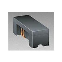
Model
Value Code (see table)
Tolerance Code
Model Suffi x
* RoHS Directive 2002/95/EC Jan 27, 2003 including Annex.
** Bourns follows the prevailing defi nition of “halogen free” in the industry. Bourns considers a product to be
Specifi cations are subject to change without notice.
Customers should verify actual device performance in their specifi c applications.
Part Number
SRF2012-670YA
SRF2012-900YA
SRF2012-121YA
SRF2012-161YA
SRF2012-181YA
SRF2012-201YA
SRF2012-221YA
SRF2012-261YA
SRF2012-361YA
Asia-Pacifi c: Tel: +886-2 2562-4117 • Fax: +886-2 2562-4116
Europe: Tel: +41-41 768 5555 • Fax: +41-41 768 5510
The Americas: Tel: +1-951 781-5500 • Fax: +1-951 781-5700
www.bourns.com
Electrical Specifi cations
Soldering Profi le
How to Order
“halogen free” if (a) the Bromine (Br ) content is 900 ppm or less; (b) the Chlorine ( Cl ) content is 900 ppm or less;
and (c) the total Bromine (Br) and Chlorine ( Cl ) content is 1500 ppm or less.
275
225
175
125
75
25
0
150°C
<1> Maximum of 10 seconds between
+255°C and +260°C
SRF2012 - 201 Y A
120
160
180
200
220
260
360
50
(Ω)
67
90
Impedance
@ 100 MHz
Ramp Up
3°C/second maximum
Tolerance
120 - 150 seconds
±25
±25
±25
±25
±25
±25
±25
±25
±25
(%)
100
Voltage
Rated
(VDC)
190°C
50
50
50
50
50
50
50
50
50
Time (seconds)
<1> 255°C
220°C
150
Withstanding
Features
■
■
■
10 seconds minimum
SRF2012A Series - Common Mode Chip Inductors
Voltage
Schematic
High impedance value
Current rating up to 400 mA
RoHS compliant* and halogen free**
(DC)
125
125
125
125
125
125
125
125
125
1
4
seconds
60 - 90
200
Resistance
Insulation
(MΩ) Min.
260°C peak
10
10
10
10
10
10
10
10
10
250
Ramp Down
6°C/second
maximum
Max.
DCR
0.25
0.35
0.35
0.45
0.3
0.3
0.4
0.4
0.4
(Ω)
Rev. 02/22/05
2
3
Max.
(mA)
IDC
400
400
400
350
350
300
300
300
300
300
Applications
■
■
■
( .022 ± .004)
Refl ow soldering .... 230 °C; 50 sec max.
Operating Temperature
Storage Temperature
Resistance to Soldering Heat
Temperature Rise ......30 °C max. at IDC
Core ..............................................Ferrite
Wire ........................... Enameled copper
Terminal ................................... Ag/Ni/Sn
Packaging .......2000 pcs. per 7-inch reel
0.55 ± 0.1
Noise suppression
Personal computers
Display panels
General Specifi cations
Materials
Product Dimensions
Recommended Layout
............................... -40 °C to +125 °C
............................... -40 °C to +125 °C
.......................... 260 °C, 10 sec. max.
(.047 ± .008)
1.2 ± 0.2
(.043)
(.006 ± .004)
1.1
0.15 ± 0.1
4
1
1
4
DIMENSIONS:
(Temperature rise included)
(.102)
2.6
(.079 ± .008)
2.0 ± 0.2
2
3
(INCHES)
MM
(.047 ± .008)
1.2 ± 0.2
2
3
(.018)
0.45
( .018 ± .004)
( .022 ± .004)
( .018 ± .004)
0.46 ± 0.1
0.55 ± 0.1
0.46 ± 0.1
(.049)
1.25


