High Current, High Frequency, Low-Profile Power Inductors
FLAT-PAC™ FP1005 Series
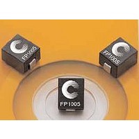
Description
• Halogen free
• 125°C maximum total temperature operation
• 10.2 x 7.0 x 4.95mm surface mount package
• Ferrite core material
• High current carrying capacity, Low core losses
• Controlled DCR tolerance for sensing circuits
• Inductance range from 85nH to 220nH
1 Open Circuit Inductance (OCL) Test Parameters: 100kHz, 0.10V rms , 0.0Adc
2 Full Load Inductance (FLL) Test Parameters: 100kHz, 0.1V rms , I sat 1
3 I rms : DC current for an approximate temperature rise of 40°C without core loss. Derating is
1208
Part Number
R1 Version
FP1005R1-R08-R
FP1005R1-R10-R
FP1005R1-R12-R
FP1005R1-R15-R
FP1005R1-R22-R
R2 Version
FP1005R2-R08-R
FP1005R2-R10-R
FP1005R2-R12-R
FP1005R2-R15-R
FP1005R2-R22-R
R3 Version
FP1005R3-R08-R
FP1005R3-R10-R
FP1005R3-R12-R
FP1005R3-R15-R
FP1005R3-R22-R
SMD Device
necessary for AC currents. PCB pad layout, trace thickness and width, air-flow and proximity of
other heat-generating components will affect the temperature rise. It is recommended the part
temperature not exceed 125°C under worst case operating conditions verified in the end
application.
BU-SB08860
7
OCL
1
± 10% (nH) FLL
100
120
150
220
100
120
150
220
100
120
150
220
85
85
85
2
Min. (nH)
108
158
108
158
108
158
61
72
86
61
72
86
61
72
86
I rms
Product Specifications
3
53
50
45
(Amps) I sat 1
4 I sat 1: Peak current for approximately 20% rolloff at +25°C.
5 I sat 2: Peak current for approximately 20% rolloff at +125°C.
6 K-factor: Used to determine B p-p for core loss (see graph). B p-p = K * L * ΔI * 10 -3 , B p-p : (Gauss),
7 Part Number Definition: FP1005Rx-Rxx-R
4
@ 25°C (Amps) I sat 2
• Current range from 33 to 90 amps
• Frequency range up to 2MHz
• RoHS compliant
Applications
• Multi-phase regulators
• Voltage Regulator Module (VRM)
• Point-of-load modules
• Desktop and server VRMs and EVRDs
• Data networking and storage systems
• Notebook regulators
• Graphics cards and battery power systems
• DCR sensing
Environmental Data
• Storage temperature range: -40°C to +125°C
• Operating temperature range: -40°C to +125°C
• Solder reflow temperature: J-STD-020D compliant
Packaging
• Supplied in tape and reel packaging, 950 parts per reel, 13” dia. reel
K: (K-factor from table), L: (inductance in nH), ΔI (peak-to-peak ripple current in amps).
(Range is application specific)
90
73
60
47
33
90
73
60
47
33
90
73
60
47
33
Page 1 of 4
• FP1005 = Product code and size
• Rxx= Inductance value in μH, R = decimal point
5
@ 125°C (Amps) DCR (mΩ) @ 20°C K-factor
Data Sheet: 4337
64
57
48
37
26
64
57
48
37
26
64
57
48
37
26
0.39 ± 7.7%
0.47 ± 6.7%
0.55 ± 5.4%
• Rx is the DCR indicator
• “-R” suffix = RoHS compliant
536
536
536
536
536
536
536
536
536
536
536
536
536
536
536
6