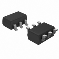
TB6078FUG(TE12L) Toshiba, TB6078FUG(TE12L) Datasheet

TB6078FUG(TE12L)
Specifications of TB6078FUG(TE12L)
Available stocks
Related parts for TB6078FUG(TE12L)
TB6078FUG(TE12L) Summary of contents
Page 1
... TOSHIBA BiCMOS Linear Integrated Circuit Silicon Monolithic Shock Sensor IC TB6066FNG detects an existence of external shock through the shock sensor and output Low-level signal at 7 pin. It has so excellent characteristic in S/N ratio that user can use Analog signal for mechanical control systems, like servo control. ...
Page 2
Pin Function Pin No. Pin Name 1 SIA Connection terminal of shock sensor 2 SOA Amp (A) output terminal 3 VR Guard terminal. Reference voltage to protect (1, 16 pin) 4 A3I OP-AMP (3) input terminal 5 A3O OP-AMP (3) ...
Page 3
Maximum Ratings Characteristics Power supply voltage Input voltage Power dissipation Storage temperature Recommend Operating Condition Characteristics Power supply voltage Operating temperature Note: The IC may be destroyed due to short circuit between adjacent pins, incorrect orientation of ...
Page 4
Electrical Characteristics (1) --- Guaranteed data (unless otherwise specified, V Characteristics Supply voltage Supply current (DIFF-AMP) Characteristics Gain Output DC voltage Output source current Output sink current (OP-AMP1) Characteristics Input voltage 1 Input current Output voltage range (Low side) Output ...
Page 5
Characteristics Symbol Input voltage 1 Input current Output voltage range (Low side) Output voltage range (High side) Output source current Output sink current (Window-Comparator) Characteristics Symbol Output pull-up resistance Output sink current (Guard Terminal) Characteristics Symbol Reference Voltage Note: ...
Page 6
... Offset voltage (OP-AMP1/3) Offset voltage (OP-AMP2) (Window-Comparator) Characteristics Trip voltage 1 Note: Toshiba can not test these tables of characteristics for all samples. Therefore Toshiba does not guarantee the data. Please use the data as reference data for customer’s application. Test Symbol Test Condition Circuit ⎯ ...
Page 7
Application Note MΩ Shock ×5 sensor 50 MΩ Qs (pC/ Figure 1 The Configuration of G-Force Sensor Amplifier Figure 1 shows the configuration of G-Force sensor amplifier. The shock sensor is ...
Page 8
Equivalent Circuit 0 CMI A1O A2O A3O 1 TB6066FNG 7 CMO 2003-05-14 ...
Page 9
Test Circuit (1) Supply current MΩ 1 SIA SIB 2 SOA SOB kΩ 4 A3I A2I 5 A3O A2O 6 CMI A1I 7 CMO A1O 8 GND VCC (2) DIFF-AMP Gain: GvBuf Step ...
Page 10
DIFF-AMP Output source current: IBso 1 16 SIA SIB 2 MΩ MΩ SOA SOB kΩ A3I A2I 5 12 A3O A2O 6 11 CMI A1I 7 10 CMO A1O ...
Page 11
OP-AMP2 Input current: Iin 1 16 SIA SIB 2 15 SOA SOB kΩ A3I A2I 5 12 A3O A2O 6 11 CMI A1I 7 10 CMO A1O 8 9 GND VCC Spec ...
Page 12
OP-AMP3 Output source current: IAso 1 16 SIA SIB 2 15 SOA SOB A3I A2I 5 12 A3O A2O CMI A1I 7 10 CMO A1O 8 9 GND VCC (17) ...
Page 13
Package Dimensions Weight: 0.07 g (typ.) 13 TB6066FNG 2003-05-14 ...
Page 14
... TOSHIBA is continually working to improve the quality and reliability of its products. Nevertheless, semiconductor devices in general can malfunction or fail due to their inherent electrical sensitivity and vulnerability to physical stress the responsibility of the buyer, when utilizing TOSHIBA products, to comply with the standards of safety in making a safe design for the entire system, and to avoid situations in which a malfunction or failure of such TOSHIBA products could cause loss of human life, bodily injury or damage to property ...


