MDP1601100KGD04 Vishay, MDP1601100KGD04 Datasheet

Resistor Networks & Arrays 16pin 100Kohms 2% Bussed

MDP1601100KGD04

Manufacturer Part Number
MDP1601100KGD04
Description
Resistor Networks & Arrays 16pin 100Kohms 2% Bussed
Manufacturer
Vishay
Series
MDPr
Datasheet

Specifications of MDP1601100KGD04

Product Type
Networks
Circuit Type
Bussed
Number Of Resistors
15
Resistance
100 KOhms
Tolerance
2 %
Power Rating
0.125 Watt (1/8 Watt)
Temperature Coefficient
+/- 100 PPM / C
Number Of Pins
16
Package / Case
DIP-16
Operating Temperature Range
- 55 C to + 125 C
Dimensions
7.87 mm W x 19.05 mm L x 3.05 mm H
Lead Spacing
2.54 mm
Termination Style
DIP
Lead Free Status / Rohs Status
No
Other names
MDP1601104G
Notes
(1)
(2)
(3)
* Pb containing terminations are not RoHS compliant, exemptions may apply
Document Number: 31511
Revision: 07-Jun-10
New Global Part Numbering: MDP1403100RGD04 (preferred part numbering format)
New Global Part Numbering: MDP1405121CGD04 (preferred part numbering format)
STANDARD ELECTRICAL SPECIFICATIONS
GLOBAL
MODEL/
NO. OF
PINS
MDP 14
MDP 16
GLOBAL PART NUMBER INFORMATION
Historical Part Number example: MDP1403101G (will continue to be accepted)
Historical Part Number example: MDP1405221271G (will continue to be accepted)
For resistor power ratings at + 25 °C see derating curves
Tighter tracking available
± 2 % standard, ± 1 % and ± 5 % available
GLOBAL
GLOBAL
MODEL
MODEL
MDP
MDP
HISTORICAL
MODEL
MDP
Thick Film Resistor Networks, Dual-In-Line, Molded DIP
SCHEMATIC
HISTORICAL
PIN COUNT
PIN COUNT
14 = 14 pin
16 = 16 pin
14 = 14 pin
16 = 16 pin
M
MODEL
M
MDP
01
03
05
01
03
05
D
D
PIN COUNT
POWER RATING
P
P
14
ELEMENT
SCHEMATIC
SCHEMATIC
03 = Isolated
01 = Bussed
00 = Special
P
0.125
0.250
0.125
0.125
0.250
0.125
PIN COUNT
terminator
1
1
05 = Dual
70 °C
W
14
4
4
For technical questions, contact:
(1)
SCHEMATIC
0
0
Consult factory
Consult factory
05
RESISTANCE
10 to 2.2M
10 to 2.2M
10 to 2.2M
10 to 2.2M
by alpha modifier
(see Impedance
RANGE
1M00 = 1.0 MΩ
680K = 680 kΩ
RESISTANCE
code, followed
RESISTANCE
10R0 = 10 Ω
Codes table)
3
5
SCHEMATIC
impedance
Ω
M = MΩ
VALUE
VALUE
K = kΩ
3 digit
R = Ω
03
1
1
RESISTANCE
VALUE 1
TOLERANCE
0
2
221
1, 2, 5
1, 2, 5
TOLERANCE
TOLERANCE
± %
0
1
S = Special
G = ± 2 %
G = ± 2 %
F = ± 1 %
J = ± 5 %
F = ± 1 %
J = ± 5 %
ff2aresistors@vishay.com
FEATURES
• Isolated,
• 0.160" (4.06 mm) maximum seated height and
• Thick film resistive elements
• Low temperature coefficient (- 55 °C to + 125 °C)
• Reduces total assembly costs
• Compatible
• Wide resistance range (10 Ω to 2.2 MΩ)
• Uniform performance characteristics
• Available in tube pack
• Compliant to RoHS directive 2002/95/EC
RESISTANCE
CODE
CODE
schematics available
rugged, molded case construction
± 100 ppm/°C
equipment
VALUE
R
C
101
(3)
RESISTANCE
G
G
VALUE 2
(- 55 °C to + 125 °C)
TEMPERATURE
271
COEFFICIENT
bussed
E04 = Lead (Pb)-free, tube
± ppm/°C
D
D
D04 = Tin/lead, tube
100
100
with
TOLERANCE
PACKAGING
PACKAGING
0
0
CODE
and
G
TOLERANCE
automatic
4
4
CODE
(- 55 °C to + 125 °C)
G
dual
MDP 01, 03, 05
TRACKING
± ppm/°C
PACKAGING
TCR
terminator
100
100
50
50
50
50
inserting
D04
Vishay Dale
Blank = Standard
Blank = Standard
(Dash Number)
(Dash Number)
(Up to 3 digits)
(Up to 3 digits)
From 1 to 999
From 1 to 999
PACKAGING
as applicable
as applicable
(2)
SPECIAL
SPECIAL
www.vishay.com
D04
WEIGHT
1.3
1.5
g
1

Related parts for MDP1601100KGD04

MDP1601100KGD04 Summary of contents

Page 1

... G = ± code, followed J = ± alpha modifier (see Impedance Codes table) 05 221 RESISTANCE RESISTANCE SCHEMATIC VALUE 1 For technical questions, contact: ff2aresistors@vishay.com MDP 01, 03, 05 Vishay Dale bussed and dual terminator with automatic inserting TCR TEMPERATURE (2) COEFFICIENT TRACKING (- 55 ° 125 ° ° 125 °C) ± ...

Page 2

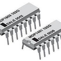
... MDP 01, 03, 05 Thick Film Resistor Networks, Dual-In-Line, Molded DIP Vishay Dale DIMENSIONS in inches (millimeters) Pin #1 Identification Pin #1 GLOBAL MODEL MDP 14 MDP 16 TECHNICAL SPECIFICATIONS PARAMETER Package Power Rating (Maximum °C) Voltage Coefficient of Resistance Dielectric Strength Insulation Resistance Operating Temperature Range Storage Temperature Range ...

Page 3

... R2 The 05 circuits are designed for TTL dual-line termination and pulse squaring. For technical questions, contact: ff2aresistors@vishay.com MDP 01, 03, 05 Vishay Dale + 125 + 150 • TTL Input Pull-down • Digital Pulse Squaring • TTL Unused Gate Pull-up • High Speed Parallel Pull-up • Long-line Impedance Balancing • ...

Page 4

... MDP 01, 03, 05 Thick Film Resistor Networks, Dual-In-Line, Molded DIP Vishay Dale PERFORMANCE TEST Power Conditioning Thermal Shock Short Time Overload Low Temperature Operation Moisture Resistance Resistance to Soldering Heat Leads immersed in + 350 °C solder to within 1/16" of device body for 3 s Shock Vibration 1000 ° ...

Page 5

... Vishay disclaims any and all liability arising out of the use or application of any product described herein or of any information provided herein to the maximum extent permitted by law. The product specifications do not expand or otherwise modify Vishay’ ...

Related keywords