4-1926733-6 TE Connectivity, 4-1926733-6 Datasheet
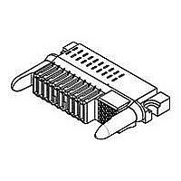
High Speed / Modular Connectors 25S 16P R/A RECPT SOCKET/RECPT CONTACT

4-1926733-6

Manufacturer Part Number
4-1926733-6
Description
High Speed / Modular Connectors 25S 16P R/A RECPT SOCKET/RECPT CONTACT
Manufacturer
TE Connectivity
Datasheets

Specifications of 4-1926733-6

Pcb Mount Alignment
Without
Pcb Mount Retention
With
Pcb Mounting Orientation
Right Angle
Make First / Break Last
Yes
Product Line
MINIPAK HDL
Ul File Number
E28476
Termination Method To Pc Board
Through Hole - Press Fit
Sealed
No
Number Of Power Positions
16
Operating Voltage Reference
AC
Operating Voltage (vac)
250
Hot Pluggable
No
Tail Length (mm [in])
3.3 [0.13]
Tail Orientation
In-line
Profile Height (y-axis) (mm [in])
8.00 [0.315]
Number Of Signal Positions
25
Number Of Positions
41
Pcb Mount Retention Type
Screw Mount
Selectively Loaded
Yes
Centerline (mm [in])
2.00 [0.079]
Centerline, Power Contacts (mm [in])
2.75 [0.108]
Underplate Material Thickness (µm [?in])
1.27 [50.000]
Length (x-axis) (mm [in])
68.21 [2.690]
Width (z-axis) (mm [in])
36.58 [1.440]
Number Of Rows
1
Mating Retention
Without
Tail Plating Material
Bright Tin-Lead
Contact Type
Socket
Contact Base Material
Copper
Contact Plating, Mating Area, Material
Gold or Palladium Nickel or Performance Based
Contact Plating, Mating Area, Thickness (µm [?in])
0.762 [30]
Tail Plating, Thickness (µm [?in])
0.5 [20]
Underplate Material
Nickel
Contact Design
Single Beam
Connector Style
Receptacle
Mating Alignment
With
Housing Material
Crystal Polymer
Ul Flammability Rating
UL 94V-0
Housing Color
Black
Mating Alignment Type
Passive Guide
Connector Contact Configuration (no. Of Pos./type)
25/Signal, 16/AC Power
Custom Configurable
No
Rohs/elv Compliance
RoHS compliant, ELV compliant
Lead Free Solder Processes
Not relevant for lead free process
Rohs/elv Compliance History
Always was RoHS compliant
Agency/standard
UL, CSA
Ul Rating
Recognized
Ul Voltage Rating (vac)
250
Csa Certified
Yes
Operating Temperature (°c [°f])
-40 – +125 [-40 – +257]
Pcb Thickness, Recommended (mm [in])
1.40 [0.055]
Applies To
Printed Circuit Board
Board-to-board Configuration
Co-Planar
Contact Transmits (typical Application)
Signal (Data)/ Power
Application Use
Board-to-Board
Pick And Place Cover
Without
Packaging Method
Tray
Lead Free Status / Rohs Status
 Details
|
1.
1.1.
1.2.
1.3.
2.
2.1.
2.2.
2.3.
3.
3.1.
©2009 Tyco Electronics Corporation
Harrisburg, PA
All International Rights Reserved.
SCOPE
Content
This specification covers perform ance, tests and quality requirem ents for MINIPAK* HDL Board Mount
Receptacle or Plug Connector System .
Qualification
W hen tests are perform ed on the subject product line, procedures specified in Figure 1 shall be used.
All inspections shall be perform ed using the applicable inspection plan and product drawing.
Successful qualification testing on the subject product line was com pleted on 20Apr09. The
Qualification Test Report num ber for this testing is 501-703. This docum entation is on file at and
available from Engineering Practices and Standards (EPS).
APPLICABLE DOCUM ENTS
The following docum ents form a part of this specification to the extent specified herein. Unless
otherwise specified, the latest edition of the docum ent applies. In the event of conflict between the
requirem ents of this specification and the product drawing, the product drawing shall take precedence.
In the event of conflict between the requirem ents of this specification and the referenced docum ents,
this specification shall take precedence.
Tyco Electronics Docum ents
!
!
!
Industry Docum ent
EIA-364: Electrical Connector/Socket Test Procedures Including Environm ental Classifications
Reference Docum ents
!
!
!
REQUIREM ENTS
Design and Construction
Product shall be of the design, construction and physical dim ensions specified on the applicable product
drawing.
109 Series: Test Specifications as indicated in Figure 1
501-703: Qualification Test Report (MINIPAK* HDL Board Mount Receptacle or Plug Connector
System )
502-1259: Engineering Report (MINIPAK* HDL Board Mount Receptacle or Plug Connector)
108-1651: Product Specification (Universal Power Module)
108-19082: Product Specification (Z-PACK 2 m m HM Connectors)
109-197: Test Specification (AMP Test Specifications vs EIA and IEC Test Methods)
* Trademark
| Indicates change
Product
Specification
MINIPAK* HDL Board Mount Receptacle or Plug Connector
System
For latest revision, visit our website at www.tycoelectronics.com\documents.
For Regional Customer Service, visit our website at www.tycoelectronics.com
108-2325
25Jun09 Rev B
1 of 9
LOC B

Related parts for 4-1926733-6

4-1926733-6 Summary of contents

Page 1

... Qualification Test Report (MINIPAK* HDL Board Mount Receptacle or Plug Connector System ) ! | 502-1259: Engineering Report (MINIPAK* HDL Board Mount Receptacle or Plug Connector) 2.2. Industry Docum ent EIA-364: Electrical Connector/Socket Test Procedures Including Environm ental Classifications 2.3. Reference Docum ents ! 108-1651: Product Specification (Universal Power Module) ! 108-19082: Product Specification (Z-PACK Connectors) ...

Page 2

... Circuit carried on 4 commoned 2 ounce layers. Further current testing results are available in 502-1259. A test system consists of 24 power contacts on 2.75 mm contact pitch and 40 signal contacts on 2.0 mm contact pitch. ...

Page 3

... DC inute hold for power contacts. Test between adjacent contacts of m ated specim ens. EIA-364-20, Condition I. 750 volts DC at sea level for signal contacts. 2500 volts DC for power contacts. Test between adjacent contacts of m ated specim ens and between closest signal and power contacts ...

Page 4

... N m axim um for power contact. Average m ating force for signal contacts shall be less than 1.65 N per contact. 0 inim um per power contact. 0. inim um per signal contact. 44 axim um per pin inim um per pin. Figure 3 (continued) 108-2325 Procedure EIA-364-70, Method 1. Stabilize at a single current level until 3 readings inute intervals are within 1 C ...

Page 5

... Power contacts: Apply axial force pin contacts in the unm ating direction axim um rate of 2. per m inute and hold for 5 seconds. Apply axial force pin contacts in the m ating direction axim um rate of 2. per m inute and hold for 5 seconds. ...

Page 6

... Procedure EIA-364-17, Method A, Test Condition 3, Test Tim e Condition C. Subject m ated specim ens for 500 hours. EIA-364-65, Class IIA (4 gas). Subject specim ens to environm ental Class IIA for 20 days (10 days unm ated followed by 10 days m ated). EIA-364-91. Subject unm ated specim ens to dust contam ination #1 (benign) for 1 hour at an airflow of 1000 cfm ...

Page 7

... Component heat resistance to wave soldering Thermal shock Humidity/temperature cycling Temperature life Mixed flowing gas Dust Final examination of product (a) See paragraph 4.1.A. NOTE (b) Test on boards. (c) Insertion only for fully loaded connectors, insertion and retention for loose power plug contacts and loose signal chicklet contacts. (d) Numbers indicate sequence in which tests are performed ...

Page 8

... Specim en Selection Specim ens shall be prepared in accordance with applicable Instruction Sheets and shall be selected at random from current production. Test groups and 10 shall each consist ated plugs and receptacles. Test group 2 shall consist ated plugs and receptacles: 5 plugs fully loaded with power and signal contacts; 5 with power contacts only; and 5 with signal contacts only ...

Page 9

Rev B Figure 5 Static Load 108-2325 ...

Related keywords