DS64EV400SQX/NOPB National Semiconductor, DS64EV400SQX/NOPB Datasheet
DS64EV400SQX/NOPB
Specifications of DS64EV400SQX/NOPB


Related parts for DS64EV400SQX/NOPB

DS64EV400SQX/NOPB Summary of contents
Page 1
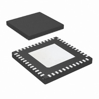
... The device uses differential current-mode logic (CML) inputs and outputs. The DS64EV400 is available 48-pin leadless LLP package. Power is supplied from either a 2.5V or 3.3V supply. Simplified Application Diagram © 2010 National Semiconductor Corporation DS64EV400 Features ■ Equalizes loss at 10 Gbps ■ ...
Page 2
Pin Descriptions Pin Name Pin # I/O, Type HIGH SPEED DIFFERENTIAL I/O IN_0 CML IN_0– 2 IN_1 CML IN_1– 5 IN_2 CML IN_2– 9 IN_3 CML IN_3– 12 OUT_0 CML ...
Page 3
Pin Name Pin # I/O, Type SERIAL MANAGEMENT BUS (SMBus) INTERFACE CONTROL PINS SDA 18 I/O, LVCMOS SDC 17 I, LVCMOS LVCMOS Other Reserv 19, 20 47,48 Note Input O = Output Connection Diagram Ordering ...
Page 4
... Absolute Maximum Ratings If Military/Aerospace specified devices are required, please contact the National Semiconductor Sales Office/ Distributors for availability and specifications. Supply Voltage ( CMOS Input Voltage CMOS Output Voltage CML Input/Output Voltage Junction Temperature Storage Temperature Lead Temperature (Soldering, 4 Seconds) Electrical Characteristics Over recommended operating supply and temperature ranges with default register settings unless other specified ...
Page 5
Symbol Parameter CML RECEIVER INPUTS (IN_n+, IN_n-) V Source Transmit Launch Signal TX Level (IN diff) V Input Threshold Voltage INTRE V Supply Voltage of Transmitter to DDTX EQ V Input Common Mode Voltage ICMDC R Differential Input Return Loss ...
Page 6
Symbol Parameter SIGNAL DETECT and ENABLE TIMING t Input OFF to ON detect — SD ZISD Output High Response Time t Input ON to OFF detect — SD IZSD Output Low Response Time t EN High to Output ON Response ...
Page 7
Electrical Characteristics — Serial Management Bus Interface Over recommended operating supply and temperature ranges unless other specified. Symbol Parameter SERIAL BUS INTERFACE DC SPECIFICATIONS V Data, Clock Input Low Voltage IL V Data, Clock Input High Voltage IH I Current ...
Page 8
System Management Bus (SMBus) and Configuration Registers The System Management Bus interface is compatible to SM- Bus 2.0 physical layer specification. The use of the Chip Select signal is required. Holding the CS pin High enables the SMBus port allowing ...
Page 9
Name Address Default Type Bit 7 0x00 0x00 RO Status 0x01 0x00 RO Status Status 0x02 0x00 RO Enable/ 0x03 0x44 RW Boost ( Enable/ 0x04 0x44 RW Boost ( 0x05 0x00 RW Signal Detect 0x06 ...
Page 10
FIGURE 1. Test Setup Diagram FIGURE 2. CML Output Transition Times FIGURE 3. Propagation Delay Timing Diagram FIGURE 4. Signal Detect (SD) Delay Timing Diagram 10 30032027 30032002 30032003 30032004 ...
Page 11
FIGURE 5. Enable (EN) Delay Timing Diagram FIGURE 6. Simplified Receiver Input Termination Circuit FIGURE 7. SMBus Timing Parameters 11 30032005 300320017 www.national.com 300320018 ...
Page 12
DS64EV400 Functional Descriptions The DS64EV400 is a programmable quad equalizer opti- mized for operation Gbps for backplane and cable applications. EQUALIZER BOOST CONTROL Each data channel support eight programmable levels of equalization boost. The state of the ...
Page 13
An output logic high indicates the presence of a signal that has exceeded the ON threshold value (called SD_ON). An output logic Low means that the input signal has fallen below the OFF threshold value (called SD_OFF). These val- ...
Page 14
DS64EV400 Applications Information UNUSED EQUALIZER CHANNELS It is recommended to put all unused channels into standby mode. GENERAL RECOMMENDATIONS The DS64EV400 is a high performance circuit capable of de- livering excellent performance. Careful attention must be paid to the details ...
Page 15
Typical Performance Eye Diagrams and Curves Figure 8. Equalized Signal (40 In FR4, 2.5Gbps, PRBS7, 0x07 Setting) Figure 10. Equalized Signal (40 In FR4, 6.4 Gbps, PRBS7, 0x06 Setting) Figure 12. Equalized Signal (30 In FR4, 10 Gbps, PRBS7, 0x06 ...
Page 16
Figure 14. Equalized Signal (32 In Tyco XAUI Backplane, 6.25 Gbps, PRBS7, 0x06 Setting) Figure 15. DJ vs. EQ Setting (10 Gbps) www.national.com 30032014 30032015 Figure 16 Setting (6.4 Gbps) 16 30032016 ...
Page 17
Physical Dimensions inches (millimeters) unless otherwise noted 48-pin LLP Package ( 0.8 mm, 0.5 mm pitch) Order Number DS64EV400SQ Package Number SQA48D 17 www.national.com ...
Page 18
... For more National Semiconductor product information and proven design tools, visit the following Web sites at: www.national.com Products Amplifiers www.national.com/amplifiers Audio www.national.com/audio Clock and Timing www.national.com/timing Data Converters www.national.com/adc Interface www.national.com/interface LVDS www.national.com/lvds Power Management www.national.com/power Switching Regulators www.national.com/switchers LDOs www.national.com/ldo LED Lighting www ...