DP4R60E20B Crydom Co., DP4R60E20B Datasheet
DP4R60E20B
Manufacturer Part Number
DP4R60E20B
Description
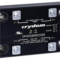
RELAY SSR CONTACT 48VDC 20A 32V
Manufacturer
Crydom Co.
Series
DPr
Datasheets
1.DP4R60D20.pdf
(7 pages)
2.DP4R60E20.pdf
(6 pages)
3.DP4R60E20.pdf
(2 pages)
4.DP4R60E20.pdf
(1 pages)
Specifications of DP4R60E20B
Circuit
SPST-NO (1 Form A)
Output Type
DC
On-state Resistance
14 mOhm
Load Current
20A
Voltage - Input
18 ~ 32VDC
Voltage - Load
1 ~ 48 V
Mounting Type
Chassis Mount
Termination Style
Screw Terminal
Package / Case
Hockey Puck
Lead Free Status / Rohs Status
Lead free / RoHS Compliant


WIRING DIAGRAM
DP Series
DC Load Reversing Solid State Contactors
FEATURES
MOUNTING INSTRUCTIONS
Please read all installation instructions before using your DP Series Solid State Contactor (SSC).
Crydom’s advanced DC Switching Technology is now conveniently packaged in a High Power
“H-Bridge” configuration with optional Soft Start/Ramp Up, Soft Stop/Ramp Down & Brake
features for use in DC Load Reversing applications including motors, brakes, clutches, electro
magnets, solenoids, plating baths and electrolytic cells. The DP Series Solid State DC Reversers
are an all-solid-state design with 2.5 Kv Optical Isolation and incorporate low dissipation power
FETs for fast and efficient Load control.
Choose one of the two mounting options and follow the instructions.
Mounting on Heat Sink
Mounting on Panel
Convenient FET switches in H-bridge configuration
Built-in protective Forward/Reverse interlock function
UL & IEC ratings for general use & Motor loads
LED Status indicators for Operating Modes
Select adequate heat sink (see thermal derating
curves).
Be sure to use thermal pad or grease between the
SSC and the selected heat sink.
DP Series Contactor mounting slots have a diameter
of 0.2 in (5.0 mm). Four screws are needed (not
included) to mount the SSC onto heat sink (See Fig.
1). Choose screw length considering the mounting
surface and that DP Series baseplate thickness is
0.125 in (3.2 mm).
Before applying full torque tighten down all 4 screws until they contact the baseplate.
Then, tighten them to 20 in-lbs (2.2 Nm) starting with one immediately followed by the one
in the diagonally opposite corner. After the first 2 screws are completely tightened,
proceed tightening the remaining 2 screws.
For optimal thermal performance heat sink fins should be oriented vertically to natural
airflow.
Locate the panel section on which the DP Series SSC will be mounted. Panel mount
surface must provide adequate heat sinking capability.
Be sure to use thermal pad or grease between the SSC and the panel.
DP Series Contactor mounting slots have a diameter of 0.2 in (5.0 mm). Four screws are
needed (not included) to mount the SSC onto panel. Choose screw length considering the
mounting surface and that DP Series baseplate thickness is 0.125 in (3.2 mm).
Before applying full torque tighten down all 4 screws until they contact the baseplate.
Then, tighten them to 20 in-lbs (2.2 Nm) starting with one immediately followed by the one
in the diagonally opposite corner. After the first 2 screws are completely tightened,
proceed tightening the remaining 2 screws.
(B)
Cell
4 / L2
1 / -
(C)
DC POWER SUPPLY SIDE
DC Power Supply
LOAD SIDE
Motor
(A)
DC
(B)
2 / +
3 / L1
mounted on HS053 heat
Resistance
fig. 1
5
6
7
8
(D)
DP Series SSC
+VCC
+FWD
+REV
GND
sink(A)
PART NUMBER NOMENCLATURE
DERATING CURVES
Series
DP
Required for valid part number
For options only and not required for valid part number
(A)
(B)
(C)
(D)
(E)
Initial Logic Supply Voltage On
Forward ON
Reverse ON
Dynamic Brake
Interlocking
DP4Rxx60x20xx
DP4Rxx60x40xx
DP4Rxx60x60xx
DP4Rxx60x20xx
DP4Rxx60x40xx
DP4Rxx60x60xx
70
60
50
40
30
20
10
0
DP4Rxx60x20xx
DP4Rxx60x40xx
DP4Rxx60x60xx
DP Series
Terminal (3/L1) is (+) during Forward operation. Terminal (4/L2) is (+) during Reverse operation.
For a complete description of available Operating Modes, see definitions on reverse side of this sheet.
See compatible accessories in TABLE 4.
For maximum ratings use heat sink ratings in TABLE 1.
Suggested Input Mating Connector/Plug : Crimp Housing, Positive Latch (Molex 050579404).
DP Series
Part No.
DP Series
20
Status Functions
Part No.
Part No.
DP4Rxx60x60xx
DP4Rxx60x40xx
DP4Rxx60x20xx
4R
Function
4R: 4 Channel DC Reversing
30
Ambient Temperature (ºC)
Required Heat Sink
Hex Screw Type 1/4-20 with lock washers
Hex Screw Type 1/4-20 with lock washers
SB
40
HK1
Screw / Clamp Combo Type 10-32
Start Mode
Blank: Start
SA: Soft Start/Ramp Up, 0.2 sec
SB: Soft Start/Ramp Up, 0.5 sec
SC: Soft Start/Ramp Up, 1 sec
TABLE 1
(B)
[ºC/W]
1.5
1.0
0.5
Output Terminal
50
60
HS053
Green LED (Forward)
Flash 3x Intermittently
Rated Operating Voltage
60: 48 VDC
60
Crydom Heat Sink
Flash Twice
Flash Once
HS103/HS103DR
HS103/HS103DR
TABLE 2
OFF
TABLE 3
ON
TABLE 4
Part No.
(E)
HS103DR
HS053
D
HS103
70
Control Voltage
D: 4.5-15 VDC
E: 18-32 VDC
Accessories
80
Maximum Torque
40
HSP-3
HSP-5
Operational Current
20: 20 Amps
40: 40 Amps
60: 60 Amps
lbs in (N m)
Yellow LED (Reverse)
20 (2.2)
25 (2.8)
25 (2.8)
Flash 3x Intermittently
Flash Twice
Flash Once
B
Stop Mode
Blank: Stop Mode matches Start Mode
B2: Dynamic Brake, 0.2 sec
B5: Dynamic Brake, 0.5 sec
B8: Dynamic Brake, 0.8 sec
B: Dynamic Brake, Continuous
OFF
ON
TRM1
for Max. Ratings
H
AWG (mm
Wire Size
Thermal Pad
Blank: Not Included
H: Included
12 (3.3)
6 (13.3)
8 (8.4)
Rev. 060211
TRM6
2
)
Related parts for DP4R60E20B
Image
Part Number
Description
Manufacturer
Datasheet
Request
R

Part Number:
Description:
RELAY SSR 10-35MA INPUT 16 DIP
Manufacturer:
Crydom Co.
Datasheet:
Part Number:
Description:
RELAY SSR 3.5-10VDC INPUT 16 DIP
Manufacturer:
Crydom Co.
Datasheet:

Part Number:
Description:
RELAY SSR 5A 480VAC SIP
Manufacturer:
Crydom Co.
Datasheet:

Part Number:
Description:
RELAY SSR 12A 240VAC DC
Manufacturer:
Crydom Co.
Datasheet:

Part Number:
Description:
RELAY SSR 25A 240VAC DC
Manufacturer:
Crydom Co.
Datasheet:

Part Number:
Description:
POWER CONTROL SSR 15A DC IN
Manufacturer:
Crydom Co.
Datasheet:
Part Number:
Description:
RELAY SSR 125A 480VAC DC INPUT
Manufacturer:
Crydom Co.
Datasheet:
Part Number:
Description:
RELAY SSR 5A 380VAC AC OUT SIP
Manufacturer:
Crydom Co.
Datasheet:
Part Number:
Description:
RELAY SSR 10A 240VAC DC
Manufacturer:
Crydom Co.
Datasheet:
Part Number:
Description:
RELAY SSR 25A 120VAC AC
Manufacturer:
Crydom Co.
Datasheet:
Part Number:
Description:
RELAY SSR 10-35MA INPUT 16 DIP
Manufacturer:
Crydom Co.
Datasheet:
Part Number:
Description:
RELAY SSR 3.5-10VDC INPUT 16 DIP
Manufacturer:
Crydom Co.
Datasheet:
Part Number:
Description:
RELAY SSR AC 2A 120VAC PNL MNT
Manufacturer:
Crydom Co.
Datasheet:

Part Number:
Description:
RELAY SSR AC OUT 1CH 0.3A PCB
Manufacturer:
Crydom Co.
Datasheet:

Part Number:
Description:
RELAY SSR 3A PC MNT W/SNUBER
Manufacturer:
Crydom Co.
Datasheet:
DP4R60E20B Summary of contents
Page 1
... LED Status indicators for Operating Modes MOUNTING INSTRUCTIONS (A) Please read all installation instructions before using your DP Series Solid State Contactor (SSC). Choose one of the two mounting options and follow the instructions. Mounting on Heat Sink Select adequate heat sink (see thermal derating curves) ...
Page 2
OPERATING MODES Start: When either FWD or REV Control signal is applied, and after Control Signal Validation Delay, DC power supply on terminals 1/- and 2/+ is directly connected to Load at terminals 3/L1 and 4/L2 with a polarity according ...