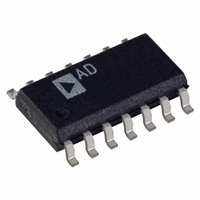
AD8184ARZ Analog Devices Inc, AD8184ARZ Datasheet - Page 10

AD8184ARZ
Manufacturer Part Number
AD8184ARZ
Description
IC VIDEO MULTIPLEXER 4X1 14SOIC
Manufacturer
Analog Devices Inc
Datasheet
1.AD8184ARZ.pdf
(12 pages)
Specifications of AD8184ARZ
Function
Video Multiplexer
Circuit
1 x 4:1
On-state Resistance
33 Ohm
Voltage Supply Source
Dual Supply
Voltage - Supply, Single/dual (±)
±4 V ~ 6 V
Current - Supply
2.1mA
Operating Temperature
-40°C ~ 85°C
Mounting Type
Surface Mount
Package / Case
14-SOIC (0.154", 3.90mm Width)
Multiplexer Configuration
4
Bandwidth
700MHz
Cross Talk
-95dB
Supply Voltage Range
± 4V To ± 6V
Operating Temperature Range
-40°C To +85°C
Tv / Video Case Style
SOIC
No. Of Pins
14
Lead Free Status / RoHS Status
Lead free / RoHS Compliant
Available stocks
Company
Part Number
Manufacturer
Quantity
Price
Company:
Part Number:
AD8184ARZ
Manufacturer:
ADI
Quantity:
455
Part Number:
AD8184ARZ
Manufacturer:
ADI/亚德诺
Quantity:
20 000
Company:
Part Number:
AD8184ARZ-REEL
Manufacturer:
RENESAS
Quantity:
831
Part Number:
AD8184ARZ-REEL
Manufacturer:
ADI/亚德诺
Quantity:
20 000
Company:
Part Number:
AD8184ARZ-REEL7
Manufacturer:
NXP
Quantity:
6 696
Part Number:
AD8184ARZ-REEL7
Manufacturer:
ADI/亚德诺
Quantity:
20 000
AD8184
EVALUATION BOARD
An evaluation board is available for the AD8184. It has been
carefully laid out and tested to demonstrate the specified high
speed performance of the devices. Figure 25 shows the sche-
matic of the evaluation board. For ordering information,
please refer to the Ordering Guide.
Figure 26 shows the silkscreen of the component side and Fig-
ure 28 shows the silkscreen of the solder side. Figures 27 and 29
show the layout of the component side and solder side respectively.
The evaluation board is provided with 49.9
tors on all inputs. This is to allow the performance to be evalu-
ated at very high frequencies where 50
popular. To use the evaluation board in video applications, the
termination resistors should be replaced with 75
The FR4 board type has the following stripline dimensions:
60-mil width, 12-mil gap between center conductor and outside
ground plane “island” and 62-mil board thickness.
The multiplexer output is loaded with a 4.99 k resistor. For
connection to external instruments, an oscilloscope probe
adapter is provided. This allows direct connection of an FET
IN0
IN2
IN3
IN1
R3
49.9
R1
49.9
R2
49.9
R4
49.9
termination is most
Figure 25. AD8184AR Evaluation Board
termination resis-
1
3
4
5
6
2
7
resistors.
GND
GND
GND
+1
+1
+1
+1
AD8184
DECODER
–10–
+V
–V
NC
S
S
probe to the board. For verification of data sheet specifications,
use of an FET probe is recommended because of its low input
capacitance. The probe adapter used on the board has the same
footprint as SMA, SMB and SMC type connectors, allowing
easy replacement if necessary.
The side-launched SMA connectors on the analog and digital
inputs can also be replaced by top-mount SMA, SMB or SMC
type connectors. When using top-mount connectors, the
stripline on the outside 1/8" of the board edge should be re-
moved with an X-acto blade as this unused stripline acts as an
open stub, which could degrade the small-signal frequency re-
sponse of the multiplexer.
Input termination resistor placement on the evaluation board is
critical to reducing crosstalk. Each termination resistor is ori-
ented so that the ground return currents flow counterclockwise
to the ground plane “island.” Although the direction of this
ground current flow is arbitrary, it is important that no two in-
put or output termination resistors share a connection to the
same ground “island.”
14
13
12
11
10
9
8
C3
C4
C2
C1
10µF
0.1µF
10µF
0.1µF
4.99k
49.9
49.9
49.9
R8
R5
R6
R7
+V
A0
A1
OUT
(SCOPE PROBE ADAPTER)
–V
S
S
REV. 0


