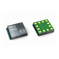
BMA250 Bosch Sensortec, BMA250 Datasheet - Page 24

BMA250
Manufacturer Part Number
BMA250
Description
3-AXIS ACCELEROMETER DIGITAL I/F
Manufacturer
Bosch Sensortec
Series
-r
Specifications of BMA250
Featured Product
BMA250 - Digital, Triaxial Acceleration Sensor
Axis
X, Y, Z
Acceleration Range
±2g, 4g, 8g, 16g
Sensitivity
256LSB/g, 128LSB/g, 64LSB/g, 16LSB/g
Voltage - Supply
1.62 V ~ 3.6 V
Output Type
I²C™, SPI™
Bandwidth
8Hz ~ 1kHz
Interface
I²C, SPI
Mounting Type
Surface Mount
Package / Case
12-VQFN
Lead Free Status / Rohs Status
Lead free / RoHS Compliant
For Use With
828-1024 - BMA250 DAUGHTERCARD FOR DEV KIT
Other names
828-1023-2
Available stocks
Company
Part Number
Manufacturer
Quantity
Price
Part Number:
BMA250
Manufacturer:
BOSCH/博世
Quantity:
20 000
Company:
Part Number:
BMA250E
Manufacturer:
AME
Quantity:
12 000
Part Number:
BMA250E
Manufacturer:
BOSCH/博世
Quantity:
20 000
Part Number:
BMA250E(F)
Manufacturer:
BOSCH/博世
Quantity:
20 000
Part Number:
BMA250E-F
Manufacturer:
BOSCH/博世
Quantity:
20 000
Company:
Part Number:
BMA250EF
Manufacturer:
TE
Quantity:
30 000
Part Number:
BMA250EF
Manufacturer:
BOSCH/博世
Quantity:
20 000
BMA250
Bosch Sensortec
Data sheet
Figure 5: Interrupt modes
Several interrupt engines can use either unfiltered or filtered acceleration data as their input. For
these interrupts, the source can be selected with the respective (0x1E) int_src_... bits, in details
these are (0x1E) int_src_data, (0x1E) int_src_tap, (0x1E) int_src_slope, (0x1E ) int_src_high,
and (0x1E) int_src_low. Setting the respective bits to ´0´ (´1´) selects filtered (unfiltered) data as
input. For the other interrupts, orientation recognition and flat detection, such a selection is not
possible. They always use filtered input data.
It is strongly recommended to set interrupt parameters prior to enabling the interrupt. Changing
parameters of an already enabled interrupt may cause unwanted interrupt generation and
generation of a false interrupt history. A safe way to change parameters of an enabled interrupt
is to keep the following sequence: disable the desired interrupt, change parameters, wait for at
least 600 s, enable the desired interrupt.
4.8.2 Mapping (inttype to INT Pin#)
The mapping of interrupts to the interrupt pins #05 or #06 is done by registers (0x19) to (0x1B).
Setting (0x19)
int1_”inttyp”
to ´1´ (´0´) maps (unmaps)
“inttyp”
to pin #5 (INT1), correspondingly
setting (0x1B)
int2_”inttyp”
to ´1´ (´0´) maps (unmaps)
“inttyp”
to pin #6 (INT2).
Note:
“inttyp”
to be replaced with the precise notation, given in the memory map in chapter 5.
Example: For flat interrupt (int1_flat): Setting (0x19)
int1_flat
to ´1´ maps
int1_flat
to pin #5
(INT1).
4.8.3 Electrical behaviour (INT pin# to open-drive or push-pull)
Both interrupt pins can be configured to show desired electrical behaviour. The ´active´ level of
each pin is determined by the (0x20) int1_lvl and (0x20) int2_lvl bits.
If (0x20) int1_lvl = ´1´ (´0´) / (0x20) int2_lvl = ´1´ (´0´), then pin #05 (INT1) / pin #06 (INT2) is
active ´1´ (´0´). In addition to that, also the electric type of the interrupt pins can be selected. By
Rev. 1.0
Page 24 / not for publishing
03 March 2011
© Bosch Sensortec GmbH reserves all rights even in the event of industrial property rights. We reserve all rights of disposal such
as copying and passing on to third parties. BOSCH and the symbol are registered trademarks of Robert Bosch GmbH, Germany.
Note: Specifications within this document are subject to change without notice.


