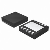
ISL54206AIRTZ-T Intersil, ISL54206AIRTZ-T Datasheet - Page 19

ISL54206AIRTZ-T
Manufacturer Part Number
ISL54206AIRTZ-T
Description
IC USB SWITCH DUAL SPDT 10TDFN
Manufacturer
Intersil
Datasheet
1.ISL54206AIRTZ.pdf
(20 pages)
Specifications of ISL54206AIRTZ-T
Function
USB Switch
Circuit
2 x SPDT
On-state Resistance
17.7 Ohm
Voltage Supply Source
Single Supply
Voltage - Supply, Single/dual (±)
2.7 V ~ 3.6 V
Current - Supply
8µA
Operating Temperature
-40°C ~ 85°C
Mounting Type
Surface Mount
Package / Case
10-TDFN Exposed Pad
Lead Free Status / RoHS Status
Lead free / RoHS Compliant
Package Outline Drawing
L10.2.1x1.6A
10 LEAD ULTRA THIN QUAD FLAT NO-LEAD PLASTIC PACKAGE
Rev 5, 3/10
(2.00)
0.10
(0.80)
2X
(10X 0.60)
B
TYPICAL RECOMMENDED LAND PATTERN
(6X 0.50 )
19
(10 X 0.20)
TOP VIEW
(1.30)
2.10
(2.50)
1
1
INDEX AREA
(0.05 MIN)
(0.10 MIN.)
PIN 1
A
8.
NOTES:
ISL54206A
1.
2.
3.
4.
5.
6.
7.
8.
PACKAGE
OUTLINE
PIN #1 ID
Dimensioning and tolerancing conform to ASME Y14.5M-1994.
All Dimensions are in millimeters. Angles are in degrees.
Dimensions in (
Unless otherwise specified, tolerance : Decimal ± 0.05
Lead width dimension applies to the metallized terminal and is measured
between 0.15mm and 0.30mm from the terminal tip.
Maximum package warpage is 0.05mm.
Maximum allowable burrs is 0.076mm in all directions.
Same as JEDEC MO-255UABD except:
No lead-pull-back, MIN. Package thickness = 0.45 not 0.50mm
Lead Length dim. = 0.45mm max. not 0.42mm.
The configuration of the pin #1 identifier is optional, but must be located within
the zone indicated. The pin #1 identifier may be either a mold or mark feature.
8.
0.10 MIN.
0.80
10
) for Reference Only.
C
MAX. 0.55
1
6X 0.50
9
0.05 MIN.
0 . 125 REF
BOTTOM VIEW
SIDE VIEW
DETAIL "X"
0-0.05
4
6
5
10 X 0.20 4
10X 0.40
SEATING PLANE
0.10
4X 0.20 MIN.
SEE DETAIL "X"
October 28, 2010
0.10 C
M
M
0.08
C
C
FN6515.3
A B
C
C


