84-8511.3620 EAO, 84-8511.3620 Datasheet - Page 32
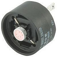
84-8511.3620
Manufacturer Part Number
84-8511.3620
Description
08N6130
Manufacturer
EAO
Datasheet
1.84-0100.0.pdf
(50 pages)
Specifications of 84-8511.3620
Contact Configuration
SPST-NO
Contact Voltage Ac Nom
42V
Contact Voltage Dc Nom
42V
Contact Current Max
20mA
Actuator Style
Round
Switch Terminals
Solder Lug
Actuator / Cap Color
Orange
Rohs Compliant
Yes


Application guidelines
When switching inductive loads such as relays, DC motors, and DC solenoids, it is always important
to absorb surges (e.g. with a diode) to protect the contacts. When these inductive loads are switched
off, a counter emf can severely damage switch contacts and greatly shorten lifetime.
Fig. 1 shows an inductive load with a free-wheeling diode connected in parallel. This free-wheeling
diode provides a path for the inductor current to flow when the current is interrupted by the switch.
Without this free-wheeling diode, the voltage across the coil will be limited only by dielectric break-
down voltages of the circuit or parasitic elements of the coil. This voltage can be kilovolts in amplitude
even when nominal circuit voltages are low (e.g. 12 VDC) see Fig. 2.
The free-wheeling diode should be chosen so that the reverse breakdown voltage is greater than the
voltage driving the inductive load. The DC blocking voltage (VR) of the free-wheeling diode can be
found in the datasheet of a diode. The forward current should be equal or greater than the maximum
current flowing through the load.
To get an efficient protection, the free-wheeling diode must be connected as close as possible
to the inductive load!
0
VDC
Suppressor circuits
+
_
Switching with inductive load
Free-wheeling
30
05.2009
Fig. 1
Switch
diode
Inductive
load
over load without free-wheeling diode
Sveral hundred
thousend volts
to several
Counter emf
0
Fig. 2
ON
OFF
e = L
__
di
dt
84
Related parts for 84-8511.3620
Image
Part Number
Description
Manufacturer
Datasheet
Request
R

Part Number:
Description:
Cap Film 260uF 400VDC PP 10% 84 X 51mm Screw Terminal Can Bulk
Manufacturer:
Kemet
Datasheet:

Part Number:
Description:
Indicator
Manufacturer:
EAO
Datasheet:


Part Number:
Description:
Switch Actuator
Manufacturer:
EAO
Datasheet:

Part Number:
Description:
Switch Actuator
Manufacturer:
EAO
Datasheet:
Part Number:
Description:
Switch Actuator
Manufacturer:
EAO
Datasheet:

Part Number:
Description:
INDICATOR, ALUMINUM
Manufacturer:
EAO
Datasheet:

Part Number:
Description:
SINGLE CHIP LED/ T1 BI-PIN/ 2.1VDC/20MA - RED
Manufacturer:
EAO
Datasheet:

Part Number:
Description:
INDICATOR, INCAND LAMP, BI PIN
Manufacturer:
EAO
Datasheet:

Part Number:
Description:
INDICATOR, BI-PIN
Manufacturer:
EAO
Datasheet:

Part Number:
Description:
INDICATOR, INCAND LAMP, MIDGET GROOVED
Manufacturer:
EAO
Datasheet: