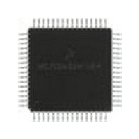
MC68HC711E9FU Freescale Semiconductor, MC68HC711E9FU Datasheet - Page 218

MC68HC711E9FU
Manufacturer Part Number
MC68HC711E9FU
Description
Manufacturer
Freescale Semiconductor
Datasheet
1.MC68HC711E9FU.pdf
(242 pages)
Specifications of MC68HC711E9FU
Cpu Family
HC11
Device Core Size
8b
Frequency (max)
4MHz
Interface Type
SCI/SPI
Program Memory Type
EPROM
Program Memory Size
12KB
Total Internal Ram Size
512Byte
# I/os (max)
38
Number Of Timers - General Purpose
8
Operating Supply Voltage (typ)
3.3/5V
Operating Supply Voltage (max)
5.5V
Operating Supply Voltage (min)
3V
On-chip Adc
8-chx8-bit
Instruction Set Architecture
CISC
Operating Temp Range
0C to 70C
Operating Temperature Classification
Commercial
Mounting
Surface Mount
Pin Count
64
Package Type
PQFP
Lead Free Status / Rohs Status
Not Compliant
Available stocks
Company
Part Number
Manufacturer
Quantity
Price
- Current page: 218 of 242
- Download datasheet (2Mb)
Common Bootstrap Mode Problems
8491 '*
8492 '*
8493 '*
8494 '************************************************************************
8500 IF K > 255 THEN HX$="Too big":GOTO 8530
8510 HX$=MID$(H$,K\16+1,1)
8520 HX$=HX$+MID$(H$,(K MOD 16)+1,1)
8530 RETURN
9499 '******************** BOOT CODE ****************************************
9500 DATA 86, 23
9510 DATA B7, 10, 02
9520 DATA 86, FE
9530 DATA B7, 10, 03
9540 DATA C6, FF
9550 DATA F7, 10, 07
9560 DATA CE, 0F, A0
9570 DATA 18, CE, E0, 00
9580 DATA 7E, BF, 00
9590 '***********************************************************************
Common Bootstrap Mode Problems
It is not unusual for a user to encounter problems with bootstrap mode because it is new to many users.
By knowing some of the common difficulties, the user can avoid them or at least recognize and quickly
correct them.
Reset Conditions vs. Conditions as Bootloaded Program Starts
It is common to confuse the reset state of systems and control bits with the state of these systems and
control bits when a bootloaded program in RAM starts.
Between these times, the bootloader program is executed, which changes the states of some systems
and control bits:
Users also forget that bootstrap mode is a special mode. Thus, privileged control bits are accessible, and
write protection for some registers is not in effect. The bootstrap ROM is in the memory map. The DISR
bit in the TEST1 control register is set, which disables resets from the COP and clock monitor systems.
Since bootstrap is a special mode, these conditions can be changed by software. The bus can even be
switched from single-chip mode to expanded mode to gain access to external memories and peripherals.
218
•
•
•
•
•
•
The SCI system is initialized and turned on (Rx and Tx).
The SCI system has control of the PD0 and PD1 pins.
Port D outputs are configured for wire-OR operation.
The stack pointer is initialized to the top of RAM.
Time has passed (two or more SCI character times).
Timer has advanced from its reset count value.
DECIMAL TO HEX CONVERSION
INPUT:
OUTPUT: HX$ - TWO CHARACTER STRING WITH HEX CONVERSION
M68HC11 Bootstrap Mode, Rev. 1.1
K - INTEGER TO BE CONVERTED
'LDAA
'STAA
'LDAA
'STAA
'LDAB
'STAB
'LDX
'LDY
'JMP
'UPPER NIBBLE
'LOWER NIBBLE
#$23
OPT2
#$FE
PORTC
#$FF
DDRC
#4000
#$E000
$BF00
make port C wire or
light 1 LED on port C bit 0
make port C outputs
2msec at 2MHz
Start of BUFFALO 3.4
EPROM routine start address
Freescale Semiconductor
Related parts for MC68HC711E9FU
Image
Part Number
Description
Manufacturer
Datasheet
Request
R

Part Number:
Description:
APPENDIX A ELECTRICAL CHARACTERISTICS
Manufacturer:
FREESCALE [Freescale Semiconductor, Inc]
Datasheet:
Part Number:
Description:
Manufacturer:
Freescale Semiconductor, Inc
Datasheet:
Part Number:
Description:
Manufacturer:
Freescale Semiconductor, Inc
Datasheet:
Part Number:
Description:
Manufacturer:
Freescale Semiconductor, Inc
Datasheet:
Part Number:
Description:
Manufacturer:
Freescale Semiconductor, Inc
Datasheet:
Part Number:
Description:
Manufacturer:
Freescale Semiconductor, Inc
Datasheet:
Part Number:
Description:
Manufacturer:
Freescale Semiconductor, Inc
Datasheet:
Part Number:
Description:
Manufacturer:
Freescale Semiconductor, Inc
Datasheet:
Part Number:
Description:
Manufacturer:
Freescale Semiconductor, Inc
Datasheet:
Part Number:
Description:
Manufacturer:
Freescale Semiconductor, Inc
Datasheet:
Part Number:
Description:
Manufacturer:
Freescale Semiconductor, Inc
Datasheet:
Part Number:
Description:
Manufacturer:
Freescale Semiconductor, Inc
Datasheet:
Part Number:
Description:
Manufacturer:
Freescale Semiconductor, Inc
Datasheet:
Part Number:
Description:
Manufacturer:
Freescale Semiconductor, Inc
Datasheet:
Part Number:
Description:
Manufacturer:
Freescale Semiconductor, Inc
Datasheet:


