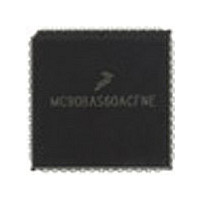
MC68HC11E1CFN3R2 Freescale Semiconductor, MC68HC11E1CFN3R2 Datasheet - Page 89

MC68HC11E1CFN3R2
Manufacturer Part Number
MC68HC11E1CFN3R2
Description
Manufacturer
Freescale Semiconductor
Datasheet
1.MC68HC11E1CFN3R2.pdf
(242 pages)
Specifications of MC68HC11E1CFN3R2
Cpu Family
HC11
Device Core Size
8b
Frequency (max)
3MHz
Interface Type
SCI/SPI
Program Memory Type
ROMLess
Program Memory Size
Not Required
Total Internal Ram Size
512Byte
# I/os (max)
38
Number Of Timers - General Purpose
8
Operating Supply Voltage (typ)
3.3/5V
Operating Supply Voltage (max)
5.5V
Operating Supply Voltage (min)
3V
On-chip Adc
8-chx8-bit
Instruction Set Architecture
CISC
Operating Temp Range
-40C to 85C
Operating Temperature Classification
Industrial
Mounting
Surface Mount
Pin Count
52
Package Type
PLCC
Lead Free Status / Rohs Status
Not Compliant
- Current page: 89 of 242
- Download datasheet (2Mb)
end of the interrupt service routine, the return-from-interrupt instruction is executed and the saved
registers are pulled from the stack in reverse order so that normal program execution can resume. Refer
to
5.5.2 Non-Maskable Interrupt Request (XIRQ)
Non-maskable interrupts are useful because they can always interrupt CPU operations. The most
common use for such an interrupt is for serious system problems, such as program runaway or power
failure. The XIRQ input is an updated version of the NMI (non-maskable interrupt) input of earlier MCUs.
Upon reset, both the X bit and I bit of the CCR are set to inhibit all maskable interrupts and XIRQ. After
minimum system initialization, software can clear the X bit by a TAP instruction, enabling XIRQ interrupts.
Thereafter, software cannot set the X bit. Thus, an XIRQ interrupt is a non-maskable interrupt. Because
the operation of the I-bit-related interrupt structure has no effect on the X bit, the internal XIRQ pin remains
unmasked. In the interrupt priority logic, the XIRQ interrupt has a higher priority than any source that is
maskable by the I bit. All I-bit-related interrupts operate normally with their own priority relationship.
When an I-bit-related interrupt occurs, the I bit is automatically set by hardware after stacking the CCR
byte. The X bit is not affected. When an X-bit-related interrupt occurs, both the X and I bits are
automatically set by hardware after stacking the CCR. A return-from-interrupt instruction restores the X
and I bits to their pre-interrupt request state.
5.5.3 Illegal Opcode Trap
Because not all possible opcodes or opcode sequences are defined, the MCU includes an illegal opcode
detection circuit, which generates an interrupt request. When an illegal opcode is detected and the
interrupt is recognized, the current value of the program counter is stacked. After interrupt service is
complete, reinitialize the stack pointer so repeated execution of illegal opcodes does not cause stack
underflow. Left uninitialized, the illegal opcode vector can point to a memory location that contains an
illegal opcode. This condition causes an infinite loop that causes stack underflow. The stack grows until
the system crashes.
The illegal opcode trap mechanism works for all unimplemented opcodes on all four opcode map pages.
The address stacked as the return address for the illegal opcode interrupt is the address of the first byte
of the illegal opcode. Otherwise, it would be almost impossible to determine whether the illegal opcode
had been one or two bytes. The stacked return address can be used as a pointer to the illegal opcode so
the illegal opcode service routine can evaluate the offending opcode.
Freescale Semiconductor
Chapter 4 Central Processor Unit
Table 5-5. Stacking Order on Entry to Interrupts
Memory Location
SP–1
SP–2
SP–3
SP–4
SP–5
SP–6
SP–7
SP–8
M68HC11E Family Data Sheet, Rev. 5.1
SP
(CPU).
CPU Registers
ACCA
ACCB
PCH
CCR
PCL
IYH
IXH
IYL
IXL
Interrupts
89
Related parts for MC68HC11E1CFN3R2
Image
Part Number
Description
Manufacturer
Datasheet
Request
R
Part Number:
Description:
Manufacturer:
Freescale Semiconductor, Inc
Datasheet:
Part Number:
Description:
Manufacturer:
Freescale Semiconductor, Inc
Datasheet:
Part Number:
Description:
Manufacturer:
Freescale Semiconductor, Inc
Datasheet:
Part Number:
Description:
Manufacturer:
Freescale Semiconductor, Inc
Datasheet:
Part Number:
Description:
Manufacturer:
Freescale Semiconductor, Inc
Datasheet:
Part Number:
Description:
Manufacturer:
Freescale Semiconductor, Inc
Datasheet:
Part Number:
Description:
Manufacturer:
Freescale Semiconductor, Inc
Datasheet:
Part Number:
Description:
Manufacturer:
Freescale Semiconductor, Inc
Datasheet:
Part Number:
Description:
Manufacturer:
Freescale Semiconductor, Inc
Datasheet:
Part Number:
Description:
Manufacturer:
Freescale Semiconductor, Inc
Datasheet:
Part Number:
Description:
Manufacturer:
Freescale Semiconductor, Inc
Datasheet:
Part Number:
Description:
Manufacturer:
Freescale Semiconductor, Inc
Datasheet:
Part Number:
Description:
Manufacturer:
Freescale Semiconductor, Inc
Datasheet:
Part Number:
Description:
Manufacturer:
Freescale Semiconductor, Inc
Datasheet:
Part Number:
Description:
Manufacturer:
Freescale Semiconductor, Inc
Datasheet:


