CM05CG1R2B50AH AVX Corporation, CM05CG1R2B50AH Datasheet - Page 10
CM05CG1R2B50AH
Manufacturer Part Number
CM05CG1R2B50AH
Description
Manufacturer
AVX Corporation
Datasheet
1.CM05CG1R2B50AH.pdf
(16 pages)
Specifications of CM05CG1R2B50AH
Capacitance
1.2pF
Tolerance (+ Or -)
0.1pF
Voltage
50VDC
Temp Coeff (dielectric)
C0G
Operating Temp Range
-55C to 125C
Mounting Style
Surface Mount
Package / Case
0402
Construction
SMT Chip
Case Style
Ceramic Chip
Failure Rate
Not Required
Wire Form
Not Required
Product Length (mm)
1mm
Product Depth (mm)
0.5mm
Product Height (mm)
0.55mm
Product Diameter (mm)
Not Requiredmm
Lead Free Status / Rohs Status
Compliant


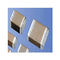
Multilayer Ceramic Chip Capacitors
Test Conditions and Standards
Test Conditions and Specifications for Temperature Compensation type (C∆ to U∆
∗1
∗2
∗3
Capacitance Value
Q
Insulation resistance (IR)
Dielectric resistance
Appearance
Termination strength
Bending strength
Vibration
test
Soldering
heat
resistance
Solderability
Temperature
cycle
Load
humidity
test
High−
temperature
with
loading
For the CF series, use 1.5 times when the rated voltage is 250V; use/ 1.2 times
when the rated voltage exceeds 630V.
2N at 0201 Size
Apply 500V for 1 minute in case the rated voltage is 630V or higher.
(∗4)
Test Items
Appearance
∆C
Q
Appearance
∆C
Q
IR
Withstand voltage (∗5)
Appearance
∆C
Q
IR
Withstand voltage (∗5)
Appearance
∆C
Q
IR
Appearance
∆C
Q
IR
(∗5)
(∗5)
(∗5)
(∗5)
(∗5)
(∗5)
Within tolerance
C≥30pF: Q≥1000
C<30pF: Q≥400+20C
10,000MΩ or 500MΩ
No problem observed
No problem observed
No problem observed
No mechanical damage at 1mm bent
No significant change is detected
Within tolerance
C≥30pF: Q≥1000
C<30pF: Q≥400+20C
No significant change is detected
±2.5% or ±0.25pF max., whichever is larger
C≥30pF: Q≥1000
C<30pF: Q≥400+20C
10,000MΩ or 500MΩ
Resists without problem
Ni/ Br termination: 90% min.
No significant change is detected
±2.5% or ±0.25pF max., whichever is larger
C≥30pF: Q≥1000
C<30pF: Q≥400+20C
10,000MΩ or 500MΩ
Resists without problem
No significant change is detected
±7.5% or ±0.75pF max., whichever is larger
C≥30pF: Q≥200
C<30pF: Q≥100+10C/ 3
500MΩ or 25MΩ
No significant change is detected
±3% or ±0.3pF max., whichever is larger
C≥30pF: Q≥350
10pF≤C<30pF: Q≥275+5C/ 2
C<10pF: Q≥200+10C
1,000MΩ or 50MΩ
Specifications (C: nominal capacitance)
•
µF min., whichever is smaller
•
µF min., whichever is smaller
•
•
•
µF min., whichever is less
µF min., whichever is smaller
µF min., whichever is samller
∗4
∗5
Except CF series.
The charge and discharge current of the capacitor must not exceed 50mA.
Measured after the rated voltage is applied for one
minute at normal room temperature and humidity. (∗3)
Microscope (10×magnification)
Apply a sideward force of 500g (5N) (∗2) to a PCB−
mounted sample.
Glass epoxy PCB (t=1.6mm); fulcrum
Spacing: 90mm; for 10 seconds.
Vibration frequency: 10 to 55 (Hz)
Amplitude: 1.5mm
Sweeping condition: 10→55→10Hz/ min.
In X, Y and Z directions:
2 hours each Total 6 hours
Soak the sample in 260°C±5°C
solder for 10±0.5 seconds
and place in a room at normal temperature
and humidity; measure after 24±2 hours.
Soaking Condition
(Cycle)
Normal room temperature (3 min.) →
Lowest operation temperature (30 min.) →
Normal room temperature (3 min.) →
Highest operation temperature (30 min.) →
After five cycles, measure after 24±2 hours.
After appling rated voltage for
500+24/ −0 hours in pre−condition at
40±2°C, humidity 90 to 95%RH allow parts
to stabilize for 48±4 hours, at room
temperature before making measurements.
After applying (∗1) twice of the rated voltage
at a temperature of 125±3°C for
1000+48/ −0 hours, measure the sample
after storing 24±2 hours.
(∗1) Apply 3 times of the rated voltage for 1 to 5 seconds.
(Preheating Conditions)
Sn63 Solder
Sn-3Ag-0.5Cu
Order
C≤1000pF
C>1000pF
1
2
Test Conditions
Temperature
150 to 200°C
80 to 100°C
•
SL Characteristics)
1MHz±10%
235±5°C
245±5°C
1kHz±10%
2±0.5 sec.
3±0.5 sec.
2 minutes
2 minutes
Time
5Vrms
0.5 to
Related parts for CM05CG1R2B50AH
Image
Part Number
Description
Manufacturer
Datasheet
Request
R

Part Number:
Description:
Manufacturer:
AVX Corporation
Datasheet:
Part Number:
Description:
Manufacturer:
AVX Corporation
Datasheet:
Part Number:
Description:
Manufacturer:
AVX Corporation
Datasheet:
Part Number:
Description:
Manufacturer:
AVX Corporation
Datasheet:
Part Number:
Description:
Manufacturer:
AVX Corporation
Datasheet: