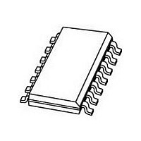
HEF4007UBT NXP Semiconductors, HEF4007UBT Datasheet

HEF4007UBT
Specifications of HEF4007UBT
Available stocks
Related parts for HEF4007UBT
HEF4007UBT Summary of contents
Page 1
DATA SHEET For a complete data sheet, please also download: The IC04 LOCMOS HE4000B Logic Family Specifications HEF, HEC The IC04 LOCMOS HE4000B Logic Package Outlines/Information HEF, HEC HEF4007UB gates Dual complementary pair and inverter Product specification File under Integrated ...
Page 2
... The HEF4007UB is a dual complementary pair and an inverter with access to each device. It has three n-channel and three p-channel enhancement mode MOS transistors. Fig.2 Pinning diagram. HEF4007UBP(N): 14-lead DIL; plastic (SOT27-1) HEF4007UBD(F): 14-lead DIL; ceramic (cerdip) (SOT73) HEF4007UBT(D): 14-lead SO; plastic (SOT108- Package Designator North America January 1995 Fig.1 Schematic diagram. PINNING ...
Page 3
Philips Semiconductors Dual complementary pair and inverter AC CHARACTERISTICS pF; input transition times SS amb L Propagation delays HIGH to LOW LOW ...
Page 4
Philips Semiconductors Dual complementary pair and inverter January 1995 Fig.3 Typical drain current I and output voltage V D functions of input voltage; V Fig.4 Typical drain current I and output voltage V D functions of input voltage; V Fig.5 ...
Page 5
Philips Semiconductors Dual complementary pair and inverter APPLICATION INFORMATION Some examples of applications for the HEF4007UB are: High input impedance amplifiers Linear amplifiers (Crystal) oscillators High-current sink and source drivers High impedance buffers. Fig.6 Voltage gain ( ...
Page 6
Philips Semiconductors Dual complementary pair and inverter Fig.9 Test set-up for measuring forward transconductance g A: average, B: average + average where ‘s’ is the observed standard deviation. Fig.10 Typical forward transconductance g January ...
Page 7
Philips Semiconductors Dual complementary pair and inverter Figures show some applications in which the HEF4007UB is used. January 1995 Fig.11 4 MHz crystal oscillator. Fig.12 High current sink driver. Fig.13 High current source driver. 7 Product specification ...
Page 8
Philips Semiconductors Dual complementary pair and inverter Fig.14 High impedance buffer. January 1995 FUNCTION TABLE for Fig.14. INPUT DISABLE Notes HIGH state (the more positive voltage LOW state (the ...


