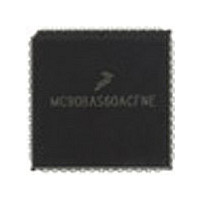
MC68HC11E0CFN3 Freescale Semiconductor, MC68HC11E0CFN3 Datasheet - Page 199

MC68HC11E0CFN3
Manufacturer Part Number
MC68HC11E0CFN3
Description
Manufacturer
Freescale Semiconductor
Datasheet
1.MC68HC11E0CFN3.pdf
(242 pages)
Specifications of MC68HC11E0CFN3
Cpu Family
HC11
Device Core Size
8b
Frequency (max)
3MHz
Interface Type
SCI/SPI
Program Memory Type
ROMLess
Program Memory Size
Not Required
Total Internal Ram Size
512Byte
# I/os (max)
38
Number Of Timers - General Purpose
8
Operating Supply Voltage (typ)
3.3/5V
Operating Supply Voltage (max)
5.5V
Operating Supply Voltage (min)
3V
On-chip Adc
8-chx8-bit
Instruction Set Architecture
CISC
Operating Temp Range
-40C to 85C
Operating Temperature Classification
Industrial
Mounting
Surface Mount
Pin Count
52
Package Type
PLCC
Lead Free Status / Rohs Status
Not Compliant
Available stocks
Company
Part Number
Manufacturer
Quantity
Price
Company:
Part Number:
MC68HC11E0CFN3
Manufacturer:
MOT
Quantity:
119
Company:
Part Number:
MC68HC11E0CFN3R2
Manufacturer:
FREESCALE
Quantity:
1 831
Main Bootloader Program
illustrates the extreme measures used in the bootloader firmware to minimize memory usage. However,
such measures are not usually considered good programming technique because they are misleading to
someone trying to understand the program or use it as an example.
After initialization, a break character is transmitted [3] by the SCI. By connecting the TxD pin to the RxD
pin (with a pullup because of port D wired-OR mode), this break will be received as a $00 character and
cause an immediate jump [4] to the start of the on-chip EEPROM ($B600 in the MC68HC711E9). This
feature is useful to pass control to a program in EEPROM essentially from reset. Refer to
Common
Bootstrap Mode Problems
before using this feature.
If the first character is received as $FF, the baud rate is assumed to be the default rate (7812 baud at a
2-MHz E-clock rate). If $FF was sent at 1200 baud by the host, the SCI will receive the character as $E0
or $C0 because of the baud rate mismatch, and the bootloader will switch to 1200 baud [5] for the rest of
the download operation. When the baud rate is switched to 1200 baud, the delay constant used to monitor
the intercharacter delay also must be changed to reflect the new character time.
At [6], the Y index register is initialized to $0000 to point to the start of on-chip RAM. The index register Y
is used to keep track of where the next received data byte will be stored in RAM. The main loop for loading
begins at [7].
The number of data bytes in the downloaded program can be any number between 0 and 512 bytes (the
size of on-chip RAM). This procedure is called "variable-length download" and is accomplished by ending
the download sequence when an idle time of at least four character times occurs after the last character
to be downloaded. In M68HC11 Family members which have 256 bytes of RAM, the download length is
fixed at exactly 256 bytes plus the leading $FF character.
The intercharacter delay counter is started [8] by loading the delay constant from TOC1 into the X index
register. The 19-E-cycle wait loop is executed repeatedly until either a character is received [9] or the
allowed intercharacter delay time expires [10]. For 7812 baud, the delay constant is 10,241 E cycles (539
x 19 E cycles per loop). Four character times at 7812 baud is 10,240 E cycles (baud prescale of 4 x baud
divider of 4 x 16 internal SCI clocks/bit time x 10 bit times/character x 4 character times). The delay from
reset to the initial $FF character is not critical since the delay counter is not started until after the first
character ($FF) is received.
To terminate the bootloading sequence and jump to the start of RAM without downloading any data to the
on-chip RAM, simply send $FF and nothing else. This feature is similar to the jump to EEPROM at [4]
except the $FF causes a jump to the start of RAM. This procedure requires that the RAM has been loaded
with a valid program since it would make no sense to jump to a location in uninitialized memory.
After receiving a character, the downloaded byte is stored in RAM [11]. The data is transmitted back to
the host [12] as an indication that the download is progressing normally. At [13], the RAM pointer is
incremented to the next RAM address. If the RAM pointer has not passed the end of RAM, the main
download loop (from [7] to [14]) is repeated.
When all data has been downloaded, the bootloader goes to [16] because of an intercharacter delay
timeout [10] or because the entire 512-byte RAM has been filled [15]. At [16], the X and Y index registers
are set up for calling the PROGRAM utility routine, which saves the user from having to do this in a
downloaded program. The PROGRAM utility is fully explained in
EPROM Programming
Utility. The final
step of the bootloader program is to jump to the start of RAM [17], which starts the user’s downloaded
program.
M68HC11 Bootstrap Mode, Rev. 1.1
Freescale Semiconductor
199


