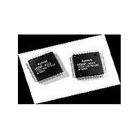
HDMP-1032 Avago Technologies US Inc., HDMP-1032 Datasheet - Page 19

HDMP-1032
Manufacturer Part Number
HDMP-1032
Description
Manufacturer
Avago Technologies US Inc.
Datasheet
1.HDMP-1032.pdf
(32 pages)
Specifications of HDMP-1032
Operating Supply Voltage (typ)
3.3V
Operating Supply Voltage (min)
3.15V
Operating Supply Voltage (max)
3.45V
Operating Temp Range
0C to 150C
Operating Temperature Classification
Commercial
Package Type
PQFP
Mounting
Surface Mount
Pin Count
64
Lead Free Status / Rohs Status
Not Compliant
Available stocks
Company
Part Number
Manufacturer
Quantity
Price
Company:
Part Number:
HDMP-1032A
Manufacturer:
AVAGO
Quantity:
1
Company:
Part Number:
HDMP-1032AG
Manufacturer:
FSC
Quantity:
30 000
Company:
Part Number:
HDMP-1032AG
Manufacturer:
AGILENT
Quantity:
155
19
HDMP-1034 (Rx) Pin Definition (continued)
CDR/Clock Generator
Name
RXCAP0
RXCAP1
REFCLK
RXDIV0
RXDIV1
RXCLK0
RXCLK1
Power Supply/Ground
V
V
V
V
GND
GND_TTL
GND_HS
GND_A
CC
CC
CC
CC
_TTL
_HS
_A
Pin
32
33
11
28
29
37
38
9
24
40
7
42
49
57
64
16
30
10
25
39
56
1
8
41
48
17
20
31
Type
C
I-TTL
I-TTL
O-TTL
S
S
S
S
S
S
S
S
Signal
Loop Filter Capacitor: A 0.1 F min. loop filter capacitor, C2, must
be connected across RXCAP0 and RXCAP1 for all combinations
of RXDIV1/RXDIV0. See Figure 12.
Reference Clock Input: The Rx PLL uses this input for frequency
lock. In addition, RX[0-15], RXFLAG, RXDATA, RXCNTL, RXREADY,
RXERROR, and RXDSLIP are clocked out on the rising edge of
REFCLK when PASSENB=1.
VCO Divider Select: These pins program the VCO divider chain
to operate at full, half, or quarter speed. See Typical Operating
Rates table and Figure 2.
Recovered Word-Rate Clock Outputs: These outputs are the PLL
recovered word rate clocks. RX[0-15], RXFLAG, RXDATA,
RXCNTL, RXREADY, RXERROR, and RXDSLIP are clocked out on
the falling edge of RXCLK1 when PASSENB=0. RXCLK0 is the
inverse of RXCLK1.
Power Supply: Normally 3.3 volts. This power supply is used for
all the core logic other than the output drivers.
TTL Power Supply: Normally 3.3 volts. Used for all TTL receiver
input and output buffer cells.
High-Speed Supply: Normally 3.3 volts. This supply is used to
provide clean references for the high-speed inputs, HSIN+
and HSIN-.
Analog Power Supply: Normally 3.3 volts. This supply is used to
feed power to the analog section of the chip.
Ground: Normally 0 volts. Tie to ground.
TTL Ground: Normally 0 volts. Tie to ground.
High-Speed Input Ground: When tied to ground, the input
impedance of HSIN+ and HSIN- are each matched to 50 . In
order to obtain high impedance (high-Z) inputs for 1:N broadcast
applications, 18 K series resistors to -5 V are recommended.
Analog Ground: Normally 0 volts. This ground is used for the
analog PLL portion of the chip.


