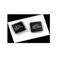
HDMP-1032 Avago Technologies US Inc., HDMP-1032 Datasheet - Page 25

HDMP-1032
Manufacturer Part Number
HDMP-1032
Description
Manufacturer
Avago Technologies US Inc.
Datasheet
1.HDMP-1032.pdf
(32 pages)
Specifications of HDMP-1032
Operating Supply Voltage (typ)
3.3V
Operating Supply Voltage (min)
3.15V
Operating Supply Voltage (max)
3.45V
Operating Temp Range
0C to 150C
Operating Temperature Classification
Commercial
Package Type
PQFP
Mounting
Surface Mount
Pin Count
64
Lead Free Status / Rohs Status
Not Compliant
Available stocks
Company
Part Number
Manufacturer
Quantity
Price
Company:
Part Number:
HDMP-1032A
Manufacturer:
AVAGO
Quantity:
1
Company:
Part Number:
HDMP-1032AG
Manufacturer:
FSC
Quantity:
30 000
Company:
Part Number:
HDMP-1032AG
Manufacturer:
AGILENT
Quantity:
155
INTERNAL
25
An external serial clock can be
used instead of the VCO clock.
This is accomplished by setting
TCLKENB high and applying
a serial rate clock to TXCLK.
Note that this mode is used for
diagnostic purposes only.
One of three frequency bands
may be selected by applying the
appropriate values to TXDIV1/0.
The VCO or TXCLK frequency
is divided by N where N is 1, 2,
or 4 based on the settings of
TXDIV1/0 as shown in the table
below. This divided version of the
VCO clock or TXCLK is used as
the serial rate clock.
N
1
2
4
Rx Operation Principles
The HDMP-1034 (Rx) is imple-
mented monolithically in a high
performance 25 GHz f
bipolar process. The Rx accepts
a serial stream of 20 bit Condi-
tional Invert with Master Transi-
tion (CIMT) line code words and
outputs parallel 16 bit/17 bit Data
Words or 14 bit Control Words.
The Rx performs the following
functions for link operation:
• Frequency Lock
• Phase Lock
• Word Synchronization
• Demultiplexing
Figure 11. HDMP-1034 (Rx) Phase-Lock Loop.
CLOCKS
REFCLK
HSIN
TXDIV1
0
0
1
FREQUENCY
DETECTOR
DETECTOR
PHASE
t
silicon
TXDIV0
0
1
X
LOCK
1
0
EXTERNAL CAP
FILTER
LOOP
• Word Decoding
• Error Detection
• Automatic Parallel Word Phase
Rx Data Path
Figure 4 shows a simplified block
diagram of the receiver. The data
path consists of an Input Sampler,
a Word Demultiplexer, a Coding
Field (C-Field) Decoder, and a
Word Field (W-Field) Decoder.
An on-chip phase-lock loop
(PLL) is used to extract timing
reference from the serial input
(HSIN ). The PLL includes a
Phase-Frequency Detector, a
Loop Filter, and a voltage con-
trolled oscillator (VCO). All the
Rx internal clock signals are gen-
erated from a Clock Generator
that is driven by either the inter-
nal VCO or an external signal,
TSTCLK, depending on whether
both RXDIV1/0 are set high.
Rx Phase-Lock Loop
A detailed block diagram for the
Rx Phase Lock Loop is shown in
Figure 11. A frequency detector
locks the VCO to the reference
clock. Once this is achieved,
a lock indication engages the
phase detector, which maintains
phase lock of the high speed in-
coming bits to that of the internal
bit clock.
The integrator, which requires
one external capacitor, controls
the frequency of the VCO. The
output of the VCO is fed into a
Adjustment
VCO
RXDIV1/0
TSTCLK
DIVIDE
BY N
GENERATOR
CLOCK
Range Selector block, which
further divides the VCO clock to
the bit rate clock. The RXDIV1/0
inputs select between divide by
1, 2, or 4 ranges, as well as a test
clock bypass mode. The bit rate
clock then drives the clock gen-
erator, which provides clocks to
the entire chip.
Rx Decoding
In Figure 4, the word
demultiplexer de-serializes the
recovered serial data from the
Input Sampler, and outputs
the resulting parallel data one
word at a time. Every word is
composed of a 16-bit Word Field
(W-Field) and a 4-bit Coding
Field (C-Field). The C-Field
(c0-c3) together with the two
center bits of the W-Field
(w7 and w8) are then decoded by
the C-Field decoder to determine
the content of the word. The
W-Field decoder is controlled by
the outputs of the C-Field de-
coder. If an inverted Data Word
or Control Word is detected, the
W-Field decoder will automati-
cally invert the W-Field data. If
a Control Word is detected, the
W-Field decoder will shift the
bottom half of the W-Field so that
the outputs are at pins RX[0-13].
RXDATA = 1 indicates that data
word is detected by the receiver.
RXCNTL = 1 indicates that a
control word is detected by the
receiver. An idle word is detected
by the receiver if RXDATA = 0,
RXCNTL = 0, and RXERROR = 0.
INTERNAL
CLOCKS


