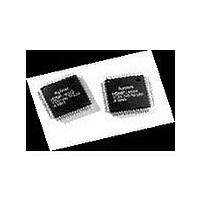
HDMP-1032 Avago Technologies US Inc., HDMP-1032 Datasheet - Page 4

HDMP-1032
Manufacturer Part Number
HDMP-1032
Description
Manufacturer
Avago Technologies US Inc.
Datasheet
1.HDMP-1032.pdf
(32 pages)
Specifications of HDMP-1032
Operating Supply Voltage (typ)
3.3V
Operating Supply Voltage (min)
3.15V
Operating Supply Voltage (max)
3.45V
Operating Temp Range
0C to 150C
Operating Temperature Classification
Commercial
Package Type
PQFP
Mounting
Surface Mount
Pin Count
64
Lead Free Status / Rohs Status
Not Compliant
Available stocks
Company
Part Number
Manufacturer
Quantity
Price
Company:
Part Number:
HDMP-1032A
Manufacturer:
AVAGO
Quantity:
1
Company:
Part Number:
HDMP-1032AG
Manufacturer:
FSC
Quantity:
30 000
Company:
Part Number:
HDMP-1032AG
Manufacturer:
AGILENT
Quantity:
155
Setting the Operating Data Rate Range
The HDMP-1032/1034 chipset
can operate from 260 MBaud to
1400 MBaud. It is divided into
three operating data ranges with
each range selected by setting
DIV1/0 as shown in the Typical
Operating Rates table. Two
examples have been provided in
order to help in understanding
and using this table.
Example 1 (Unique Range)
It is desired to transmit a 16 bit
parallel word operating at a fre-
quency of 60 MHz (60 MWord/
sec). Both the Tx and Rx must
be set to a range that covers this
word rate. According to the table
only a setting of DIV1/0 = (0/0)
allows a parallel input word rate
of 40 to 70 MHz. This range
setting easily accommodates the
required 60 MHz word rate and
HDMP-1032 (Tx), HDMP-1034 (Rx)
Typical Operating Rates
Tc = –20 C to +85 C, V
Figure 2. Typical data rates showing ranges of operation
Notes:
1. All values in this table and graph are typical unless otherwise noted by (min) or (max), (min) indicates a minimum guaranteed value,
(max) indicates a maximum guaranteed value.
2. All values in this table are expected for a BER less than 10
4
DIV1
0
0
1
0/0
0/1
1/0
DIV0
0
1
0
260 (MIN.)
100
CC
1,2
5
= 3.15V to 3.45V
400
Parallel Word Rate
(MWord/sec)
40
20
13 (min)
Range
500
25
is unique. The user serial data
rate is calculated as:
Serial Data Rate =
(–––––) (–––––) =
960 MBits/sec
The baud rate includes an addi-
tional four encoding bits (20 bits
total) that the HDMP-1032/34
G-Link chipset transmits. The
serial baud rate is calculated as:
Example 2 (Overlapping Ranges)
Some applications may have a
parallel word rate that seems
to fit in two ranges of opera-
tion. For example, a 42.5 MHz
(42.5 MWord/s) parallel data
rate falls within two ranges:
DIV1/0 = (0/0) and DIV1/0 =
(0/1). According to the table, a
setting of DIV1/0 = (0/1) gives
Serial Baud Rate =
(–––––) (–––––) =
1200 MBaud
16bits
520
Word
20bits
Word
70 (max)
45
26
1
.
800
SERIAL BAUD RATE (MBaud)
-14
.
60MW
WORD RATE (MWords/sec)
60MW
sec
sec
900
1000
50
Serial Data Rate
(MBits/sec)
640
320
208 (min)
Range
1120 (max)
720
416
1400 (MAX.)
1500
75
an upper rate of 45 MHz while a
setting of DIV1/0 = (0/0) gives a
lower rate of 40 MHz. The upper
and lower data rates stated in the
tables are typical values unless
indicated by (min) or (max) and
may vary between individual parts.
However, each transmitter/receiver
has overlapping ranges of opera-
tion providing continuous band
coverage from 260 to 1400 MBaud.
In this example, each transmitter/
receiver will permit a 42.5 MHz
parallel data rate but it is sug-
gested that DIV0 be tied to a
jumper that can be set either to
logic ‘1’ (open allowing DIV0 to
float high) or logic ‘0’ (ground).
This allows the design to accom-
modate both ranges for maximum
flexibility. This technique is rec-
ommended whenever operating
near the upper and lower ends of
two adjacent word rate ranges.
Serial Baud Rate
(MBaud)
800
400
260 (min) 520
Range
2000
100
1400 (max)
900


