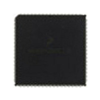
MC68HC711KS2CFN3 Freescale Semiconductor, MC68HC711KS2CFN3 Datasheet - Page 132

MC68HC711KS2CFN3
Manufacturer Part Number
MC68HC711KS2CFN3
Description
Manufacturer
Freescale Semiconductor
Datasheet
1.MC68HC711KS2CFN3.pdf
(290 pages)
Specifications of MC68HC711KS2CFN3
Cpu Family
HC11
Device Core Size
8b
Frequency (max)
4MHz
Interface Type
SCI/SPI
Program Memory Type
ROM
Program Memory Size
32KB
Total Internal Ram Size
1KB
# I/os (max)
51
Number Of Timers - General Purpose
8
Operating Supply Voltage (typ)
5V
Operating Supply Voltage (max)
5.5V
Operating Supply Voltage (min)
4.5V
On-chip Adc
8-chx8-bit
Instruction Set Architecture
CISC
Operating Temp Range
-40C to 85C
Operating Temperature Classification
Industrial
Mounting
Surface Mount
Pin Count
68
Package Type
PLCC
Lead Free Status / Rohs Status
Not Compliant
Available stocks
Company
Part Number
Manufacturer
Quantity
Price
Company:
Part Number:
MC68HC711KS2CFN3
Manufacturer:
NSC
Quantity:
1 001
- Current page: 132 of 290
- Download datasheet (4Mb)
Resets and Interrupts
5.8.3 Slow Mode
Technical Data
132
Address: $002E
DLY — Enable Oscillator Startup Delay Bit
Slow mode is a software selectable feature on M68HC(7)11KS devices
that allows the user to connect, under software control, an extra
divide-by-16 between the oscillator and the internal clock. This feature
permits a slow down of all the internal operations reducing power
consumption.
When WAI is used for power reduction, the slow mode helps further
reduce the power. Control of slow mode is performed in the system
configuration options 3 register (OPT3). See
SM — Slow-Mode Enable Bit
Reset:
Read:
Write:
Figure 5-12. System Configuration Options 3 Register (OPT3)
This bit is set during reset and can be written only once during the first
64 E-clock cycles after reset in normal modes. This bit can be used to
inhibit the oscillator startup delay after reset when using an external
clock source.
Read and write at any time
Freescale Semiconductor, Inc.
For More Information On This Product,
0 = No stabilization delay on exit from STOP
1 = Stabilization delay enabled on exit from STOP
1 = When the SM bit is asserted, a 16-clock divider is connected
0 = When the SM bit is negated, the divider is disconnected and the
Bit 7
between the oscillator and the internal clock. This causes the
system clock to run 16 times slower than normal. All modules
of the MCU slow down, including the timer, SCI, SPI, and A/D.
It is also cleared in hardware when entering stop mode or when
reset, including POR, is asserted low.
system runs at normal bus speed.
0
Go to: www.freescale.com
Resets and Interrupts
SM
6
0
5
0
4
0
3
0
Figure
2
0
5-12.
M68HC11K Family
1
0
MOTOROLA
Bit 0
0
Related parts for MC68HC711KS2CFN3
Image
Part Number
Description
Manufacturer
Datasheet
Request
R

Part Number:
Description:
APPENDIX A ELECTRICAL CHARACTERISTICS
Manufacturer:
FREESCALE [Freescale Semiconductor, Inc]
Datasheet:
Part Number:
Description:
Manufacturer:
Freescale Semiconductor, Inc
Datasheet:
Part Number:
Description:
Manufacturer:
Freescale Semiconductor, Inc
Datasheet:
Part Number:
Description:
Manufacturer:
Freescale Semiconductor, Inc
Datasheet:
Part Number:
Description:
Manufacturer:
Freescale Semiconductor, Inc
Datasheet:
Part Number:
Description:
Manufacturer:
Freescale Semiconductor, Inc
Datasheet:
Part Number:
Description:
Manufacturer:
Freescale Semiconductor, Inc
Datasheet:
Part Number:
Description:
Manufacturer:
Freescale Semiconductor, Inc
Datasheet:
Part Number:
Description:
Manufacturer:
Freescale Semiconductor, Inc
Datasheet:
Part Number:
Description:
Manufacturer:
Freescale Semiconductor, Inc
Datasheet:
Part Number:
Description:
Manufacturer:
Freescale Semiconductor, Inc
Datasheet:
Part Number:
Description:
Manufacturer:
Freescale Semiconductor, Inc
Datasheet:
Part Number:
Description:
Manufacturer:
Freescale Semiconductor, Inc
Datasheet:
Part Number:
Description:
Manufacturer:
Freescale Semiconductor, Inc
Datasheet:
Part Number:
Description:
Manufacturer:
Freescale Semiconductor, Inc
Datasheet:


